2 timer b 16-bit capture mode, 2 timer b 16-bit capture mode -5, Maxq family user’s guide: maxq8913 supplement – Maxim Integrated MAXQ Family Users Guide: MAXQ8913 Supplement User Manual
Page 80
MAXQ Family User’s Guide:
MAXQ8913 Supplement
21-5
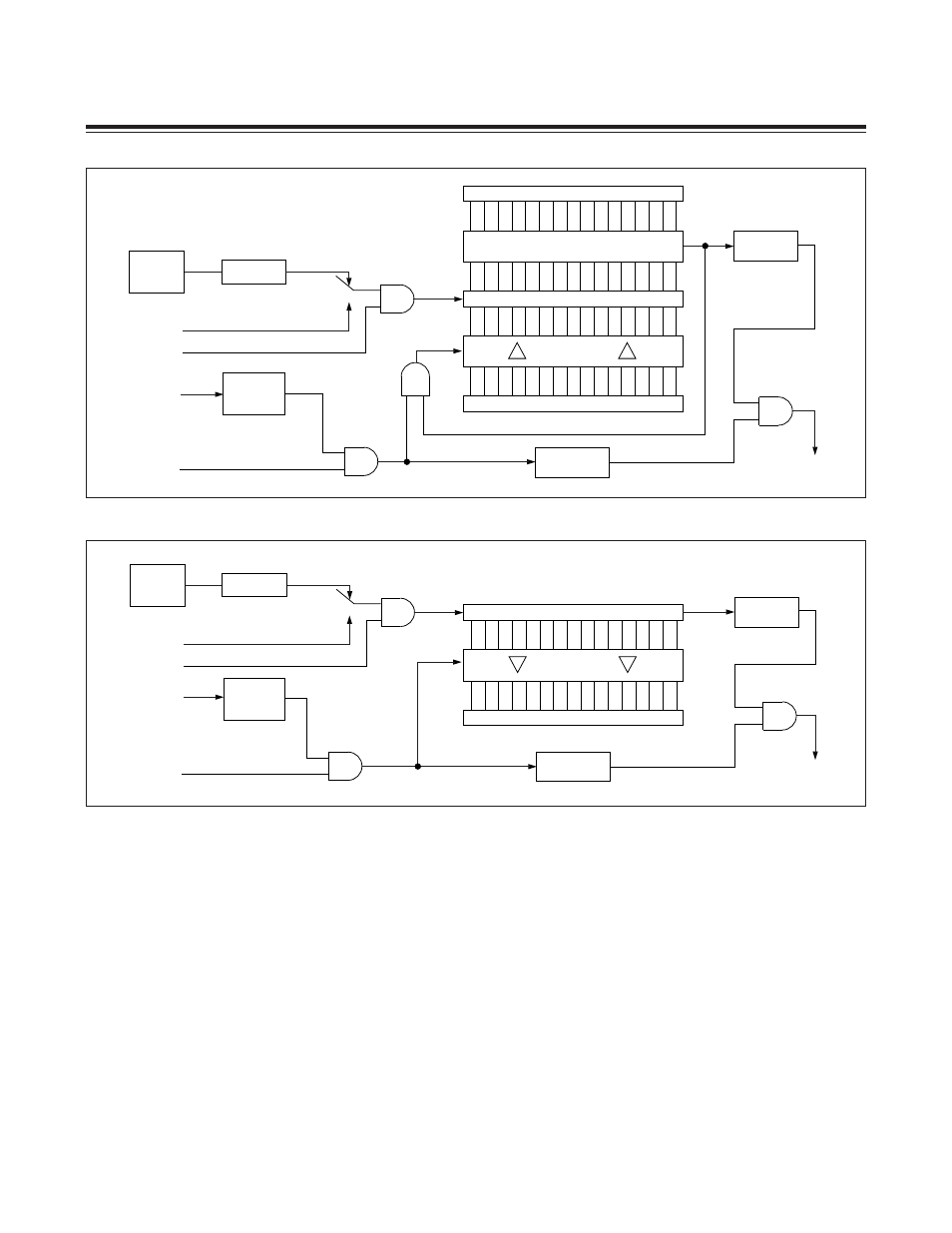
21.2.2 Timer B 16-Bit Capture Mode
The 16-bit capture mode of Timer B is configured by setting the CP/RLB bit of the control register (TBCN.0) to 1. A
functional diagram of this mode is shown in Figure 21-2. When the timer is enabled in this mode, it begins counting
up from the value contained in the TBV register until reaching an overflow state, i.e., FFFFh
→ 0000h; at which point
it sets the TBF flag (TBCN.7) and continues counting upward. When the TBF flag is set, it can generate an interrupt if
enabled. This count cycle is repeated without processor intervention as long as the timer is enabled. As the counting
proceeds, the value in the TBV register is captured in the capture/reload register (TBR) if and when a high-to-low transi-
tion occurs on the TB0B pin and the EXENB bit of the control register (TBCN.3) is set to 1. The EXFB flag (TBCN.6) is
also set when the capture occurs, and this flag can generate an interrupt if enabled. If the EXENB bit is cleared to 0,
transitions on the TB0B pin do not cause a capture event.
Figure 21-1. Timer B Autoreload Mode Block Diagram
Figure 21-2. Timer B 16-Bit Capture Mode Block Diagram
EXFB = TBCN.6
TFB = TBCN.7
TIMER B
INTERRUPT
15
0
15
0
RELOAD
FALLING
EDGE
TB0B PIN
EXENB = TBCN.3
TBR
TBV
0000h
1
TB0A PIN
TRB = TBCN.2
/CLK
COMPARE
0
SYSTEM
CLOCK
2
(2 x TBPS[2:0])
TBPS[2:0] = TBCN[10:8]
C/TB = TBCN.15
15
0
0
15
TBV
TBR
CAPTURE
0
1
TB0A PIN
TRB = TBCN.2
/CLK
TIMER B
INTERRUPT
TB0B PIN
EXENB = TBCN.3
SYSTEM
CLOCK
C/TB = TBCN.15
EXFB = TBCN.6
TFB = TBCN.7
FALLING
EDGE
2
(2 x TBPS[2:0])
TBPS[2:0] = TBCN[10:8]
Maxim Integrated