1 system register descriptions, 1 processor status flags register (psf, m8[04h]), 2 interrupt mask register (imr, m8[06h]) – Maxim Integrated MAXQ Family Users Guide: MAXQ8913 Supplement User Manual
Page 25: 1 system register descriptions -3, Maxq family user’s guide: maxq8913 supplement
MAXQ Family User’s Guide:
MAXQ8913 Supplement
4-3
4.1 System Register Descriptions
This section details the functionality of any system register contained in the MAXQ8913 that operates differently from its
description in the MAXQ Family User’s Guide. Addresses for all system and peripheral registers are given as “Mx[yy],”
where x is the module number (from 0 to 15 decimal) and yy is the register index (from 00h to 1Fh hexadecimal). Fields
in the bit definition tables are defined as follows:
• Name: Symbolic names of bits or bit fields in this register.
• Reset: The value of each bit in this register following a standard reset. If this field reads “unchanged,” the given bit
is unaffected by standard reset. If this field reads “s,” the given bit does not have a fixed 0 or 1 reset value because
its value is determined by another internal state or external condition.
• POR: If present this field defines the value of each bit in this register following a power-on reset (as opposed to a
standard reset). Some bits are unaffected by standard resets and are set/cleared by POR only.
• Access: Bits can be read-only (r) or read/write (rw). Any special restrictions or conditions that could apply when
reading or writing this bit are detailed in the bit description.
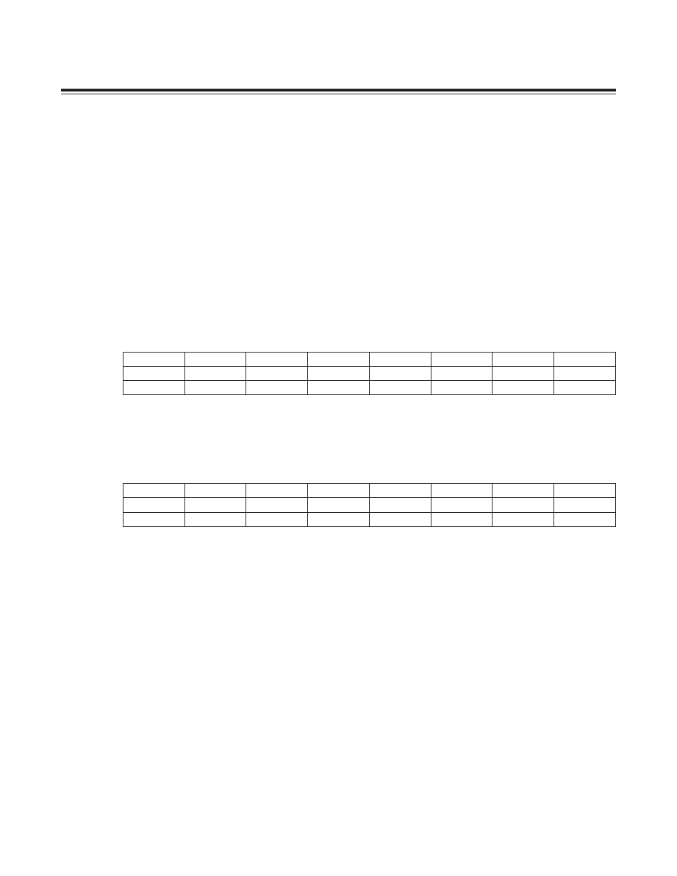
4.1.1 Processor Status Flags Register (PSF, M8[04h])
This register operates as described in the MAXQ Family User’s Guide, with the exception that the overflow bit (OV)
can be written by software.
4.1.2 Interrupt Mask Register (IMR, M8[06h])
The first four bits in this register are interrupt mask bits for modules 0 to 3, one bit per module. The eighth bit, IMS,
serves as a mask for any system module interrupt sources. Setting a mask bit allows the enabled interrupt sources for
the associated module or system (with IMS) to generate interrupt requests. Clearing the mask bit effectively disables
all interrupt sources associated with that module or, in the case of IMS, all system interrupt sources. The IMR register
is intended to facilitate user-definable interrupt prioritization.
Bit 7: System Module Interrupt Mask (IMS)
Bits 6:4: Reserved
Bit 3: Module 3 Interrupt Mask (IM3)
Bit 2: Module 2 Interrupt Mask (IM2)
Bit 1: Module 1 Interrupt Mask (IM1)
Bit 0: Module 0 Interrupt Mask (IM0)
Bit #
7
6
5
4
3
2
1
0
Name
Z
S
—
GPF1
GPF0
OV
C
E
Reset
0
0
0
0
0
0
0
0
Access
r
r
r
rw
rw
rw
rw
rw
Bit #
7
6
5
4
3
2
1
0
Name
IMS
—
—
—
IM3
IM2
IM1
IM0
Reset
0
0
0
0
0
0
0
0
Access
rw
r
r
r
rw
rw
rw
rw
Maxim Integrated
Maxim Integrated