6 troubleshooting, English, Chapter 6 troubleshooting – KEYENCE SL-R12EX User Manual
Page 71
Chapter 6 Troubleshooting
6-1
ENGLISH
6
6 Troubleshooting
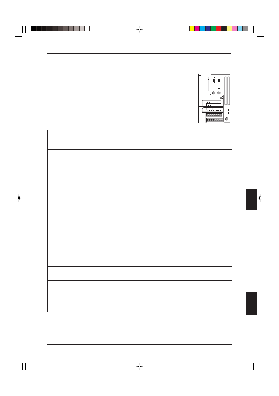
When the SL-C Series, the SL-R11, or the SL-R12EX experiences an error, it is
possible to determine the cause of the error by referring to the blinking MODE
STATUS indicators on the SL-R12EX.
The light curtain can be returned to the normal operation by turning the SL-R12EX
OFF and then back ON after the cause of the error has been removed.
Description
Causes and solutions
Blinking
indicator(s)
The SL-C Series has some error. See “5 Troubleshooting” (
➮ 5-1) in the SL-C Series instruction
manual.
Either the number of units connected in series or using light interference prevention
connections has exceeded the allowable number, or the total number of beam axes on SL-C
Series units connected in series or using light interference prevention connections is 192 or
higher. Reduce the number of units or total number of beam axes so that it falls within the
allowable range. See “3-5 Series Connection” (
➮ 3-4) and “3-6 Connection for Light Interference
Prevention (Parallel Connection)” (
➮ 3-5) in the SL-C Series instruction manual for more
information about series and light interference prevention connections.
The function switch settings are incorrect. Configure the function switches properly after
referring to the method for configuring each function in “4 Wiring and setting” (
➮ 4-1) in this
instruction manual.
The E-STOP input switch is broken, or there is a loose or broken wiring connection. Replace
the switch or redo the device wiring as appropriate as described in “4-3-2 Wiring to E-STOP
Input Terminals” (
➮ 4-5) in the SL-R11 instruction manual.
• Check for incorrect wiring, broken wiring, or loose connections for the light interference
prevention cables.
• Use specified cables as described in “4-4 About the Light Interference Prevention Connection”
(
➮ 4-9) in the SL-R11 instruction manual when wiring the system or extending its wiring.
• If the system is wired so that the light interference prevention cables are protruding from their
shielded cables, make the protruding lengths as short as possible.
• If the light interference prevention cables are connected using a terminal block, connect them
directly without going through the terminal block.
• If light interference prevention connections have been made, the main/sub switch is set so
that there are multiple main units configured. Always configure the system so that there is
only 1 main unit, as described in section “4-3-4 Connecting to Main/Sub Select Input
Terminal” (
➮ 4-7) in the SL-R11 instruction manual.
• If the SL-C unit has been configured as a sub unit with the light interference prevention
connection, the power has been cut to the SL-C unit that is configured for either the main unit
or the sub unit that is connected closer to the main unit. Be careful not to cut power to only
some of the connected SL-C units.
• The SL-R11's FSD has failed due to welded contact or a similar cause. Replace the relay
board as described in section “6-2 Relay Circuit Board Replacement” (
➮ 6-1) in the SL-R11
instruction manual.
• Confirm that the relay circuit board has been installed properly as described in section “6-2
Relay Circuit Board Replacement” (
➮ 6-1) in the SL-R11 instruction manual.
• The cable connected to the SL-C Series has transmitter and receiver ends reversed. Connect
the cable properly as described in section “2-3-1 Connecting Cable Installation” (
➮ 2-7) in the
SL-C Series instruction manual.
• The OSSD is damaged. Replace the SL-C unit.
1
SL-C Series error
2
Communication error
3
5
Total number of
beam axes is too high
4 and 14
4 and 15
4 and 16
FSD error
Function switch error
6
OSSD error
7
E-STOP input error
UNIT
BEAM
113-128
97-112
81-96
65-80
49-64
33-48
17-32
1-16
4
3
2
1
CLEAR/
BLOCKED
MODE
STATUS
BLANKING
FIXED
FLOATING
B.B.P
1
2
3
P.M.
BANK
SET/TEACH PROG.
RUN
TEACHING
1 2 3 4 5 6 7 8
1 2 3 4 5 6 7 8
1
2
3
4
5
6
7
8
9
10
11
12
13
14
15
16
1
2
3
4
5
6
7
8
9
10
11
12
13
14
15
16
MUTE A
C A1 A2
MUTE B
C B1 B2
LAMP
PMB A
C A1 A2 A3
PMB B
C B1 B2 B3
06_R12EX_E.p65
14.9.11, 0:22 PM
1