4 blanking blind protection function, 4-1 blanking blind protection unit, English – KEYENCE SL-R12EX User Manual
Page 42: English 4-4 blanking blind protection function
Chapter 4 Wiring and setting
4-4
4
English
ENGLISH
4-4 Blanking blind protection function
Note that this function can only be used in the SL-C**H Series.
WARNING
Enabling the blanking blind protection function does not necessarily remove all
hazardous zones allowing human approach. Depending on the target machine,
installation of the blanking blind protection unit may result in the new creation of
one or more hazardous zones allowing human approach. Carefully read this
section before installing or using this unit. When installing the SL-C Series into/onto
a machine, always follow the instructions in the SL-C Series Instruction Manual.
Failure to do so may result in significant harm to machine operators, including
serious injury or death.
4-4-1 Blanking blind protection unit
A single pair of blanking blind protection units (called “BBP units” hereinafter) can be connected to the SL-
R12EX. Furthermore, the BBP units cannot be a SL-C series unit for series connection.
Two types of BBP units are available: the SL-C08SB and the SL-C16SB. You can select either type appropri-
ate for your application based on the height of the obstacle of the machine. See “4-4-3 Obstacle restrictions”
(
➮4-7) for more information about the height of the obstacle.
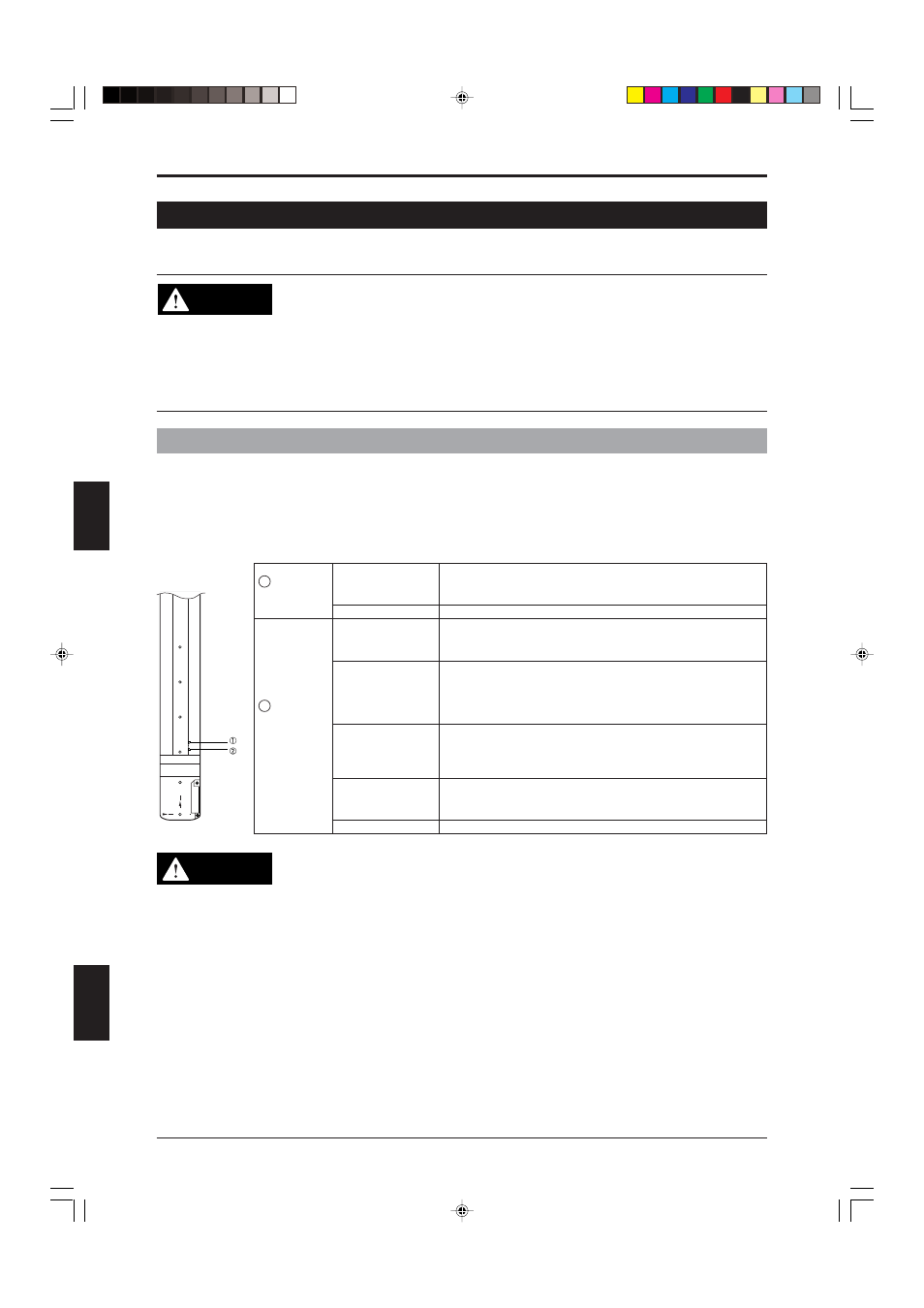
Part names
LOCKOUT
CLEAR /
BLOCKED
CLEAR /
BLOCKED
Lockout
indicator
Status
indicator
The BBP unit is in the lockout condition and the FSD is OFF-
state. See “6 Troubleshooting” for information about possible
causes of this condition.
The BBP unit is not in the lockout condition.
The BBP receiver unit is receiving all beams from the SL-C
Series transmitter. This is completely stable detection level
(more than 110%).
The BBP receiver unit is receiving all beams from the SL-C
Series transmitter, however, this is not a stable detection level
(100 to 110%). Align the beam axes and/or sensor positions
so that the indicator lights green. There is no pattern of this
indication on BBP transmitter.
The BBP receiver unit is not receiving some beams from the
SL-C Series transmitter. This is an unstable detection level.
Align the beam axes and/or sensor positions so that the
indicator turns green.
The BBP receiver unit is receiving no beams from the SL-C
Series transmitter. Align the beam axes and/or sensor
positions so that the indicator turns green.
The BBP unit is not power-supplied.
Lights (orange)
OFF
Lights (green)
Flashing (green)
(no indication on
BBP transmitter)
Flashing (red)
Lights (red)
OFF
1
2
CAUTION
• Use only E-to-E mounting brackets (OP-42370) when installing the BBP unit on
target machinery. Brackets other than the E-to-E bracket will block the SL-C
Series beam axes, preventing them from being properly received.
• There are restrictions on the order in which system devices must be turned on
when the BBP function is used along with a light interference prevention connec-
tion in configurations that also meet the following conditions. (See the SL-R11
Instruction Manual for more information about light interference prevention
connections.
1. When there are 3 sets (Main, Sub 1, and Sub 2) of light interference preven-
tion connections, and the total number of beam axes on the BBP units used
with the Main and Sub 1 units is 24 or higher;
2. When there are 4 sets (Main, Sub 1, Sub 2, and Sub 3) of light interference
prevention connections, and the total number of beam axes on the BBP units
used with the Main, Sub 1, and Sub 2 units is 16 or higher.
If your system meets the conditions described in either (1) or (2) above, you
should power on devices in the following order: Main, Sub 1, Sub 2, Sub 3. Wait
at least 1 second after turning each device on.