2 system voltage drop, System voltage drop – Rice Lake iQUBE2 Digital Diagnostic Junction Box User Manual
Page 63
Appendix
59
8.3.2 System Voltage Drop
Once the current draw of the system is calculated, the voltage input to an externally-powered iQUBE
2
system can
also be calculated.
The primary sources of voltage drop in an externally powered iQUBE
2
system are the transient boards and the
power cable. Both voltage drops are directly proportional to the current draw of the system being powered.
Transient Board Voltage Drop
The inductive chokes on the transient boards have a resistance value of 0.08
. With two chokes per board (voltage
source and return path), the effective resistance per board is 0.16
.
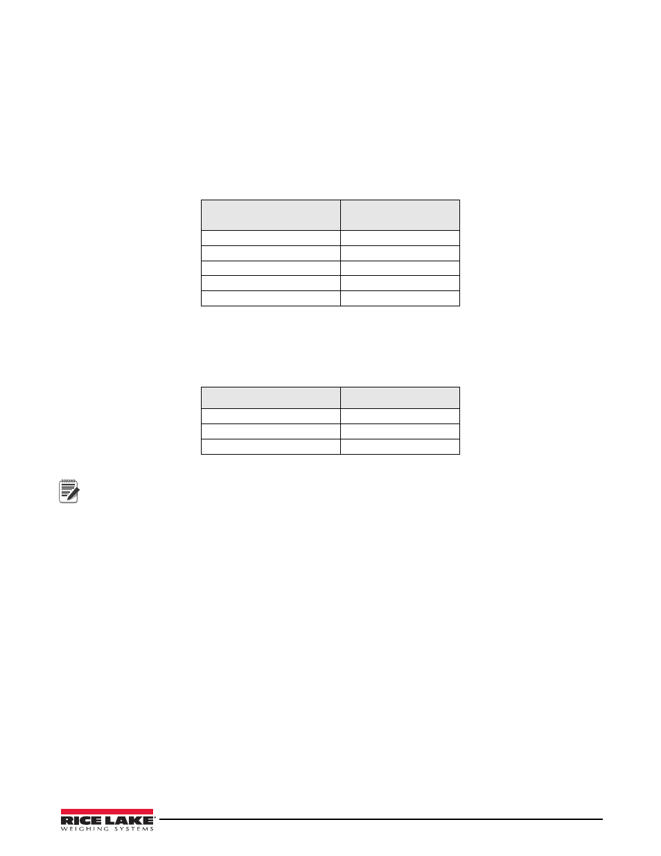
Table 8-3 lists transient board voltage drops for various system current loads.
Power Cable Voltage Drop
Power cable voltage drop is a function of the type of cable used and the length of the cable run. The run length
includes both the supply and return lengths. Table 8-4 lists cable resistance values for several gauges of stranded
wire.
Cable resistance is also a function of temperature. Values given assume an ambient temperature of 25°C (77°F).
Voltage Drop Example
Using the total system current draw from the truck scale current draw example above (Section 8.3.1 on page 58),
the voltage drop for an externally-powered system can be calculated.
Given that the current draw is 1.275A (1275 mA); the power cable is 20-gauge stranded wire; and the iQUBE
2
at
the scale is located 200 feet from the 12 VDC supply in the scale house, three voltage drops can be calculated:
• Power supply transient board voltage drop:
1.275A x 0.16
= 0.204 V
• Power cable voltage drop:
1.275A x 0.01015
/ft
x (2 x 200ft) = 5.177 V
• iQUBE
2
transient board voltage drop:
1.275A x 0.16
= 0.204 V
Total voltage drop is:
0.204 V + 5.177 V + 0.204 V = 5.585 V
Effective power supply voltage seen at the iQUBE
2
is then:
12 V – 5.585 V = 6.415 V
This voltage is acceptable, but note that the power cable voltage drop could be cut in half by using two 20-gauge
wires for both the supply and return cable runs. Cabling can be doubled by wiring to both V+ terminals and both
V– terminals on the transient board connectors. In this example, reducing the cable voltage drop to 2.589 V would
result in an effective input voltage of 9.003 V.
Current Load
Transient Board
Voltage Drop
1.0 A
0.16 V
1.5 A
0.24 V
2.0 A
0.32 V
2.5 A
0.40 V
3.0 A
0.48V
Table 8-3. Transient Board Voltage Drop
Stranded Wire Gauge
per Foot
20 ga
0.01015
18 ga
0.00639
16 ga
0.00402
Table 8-4. Common Cable Resistance Values (
/ft)
Note