3 revolution iii configuration, 1 revolution iii configuration, Revolution iii configuration – Rice Lake iQUBE2 Digital Diagnostic Junction Box User Manual
Page 35
Configuration
31
3.3
Revolution III Configuration
The Revolution III configuration utility can be used to set iQUBE
2
configuration parameters for use with any indi-
cator. When Revolution III configuration is complete, configuration data is downloaded to the iQUBE
2
.
Revolution III supports both uploading and downloading of iQUBE
2
configuration data. This capability allows con-
figuration data to be retrieved from one iQUBE
2
, edited, then downloaded to another. Revolution III provides
online help for each of its configuration displays.
To use Revolution III, do the following:
1. Install Revolution III on a PC running Windows
®
98 or later.
2. With both the iQUBE
2
and the PC powered off, connect the PC serial port to pins 1, 2, and 5 of connector J7
on the iQUBE
2
connector board. (See Table 2-2 on page 8).
3. Power up the PC and the iQUBE
2
. Use the setup switch to place the iQUBE
2
in setup mode.
4. Start the Revolution III program.
3.3.1 Revolution III Configuration
To configure the iQUBE
2
using Revolution:
1. With the PC and iQUBE
2
connected and
Revolution III running, select
New
from the
File
menu.
2. From the Select Indicator window, double-
click the iQUBE
2
icon, or select it and click
the
New Configuration File
radio button, then
click
OK
. The iQUBE
2
Information Display
is shown.
3. Select
Base Configuration
from the left pane
(see Figure 3-17) to expand it. The Base
Configuration selections (
General, Load
Cells, Load Cell Assignment, Comm Ports, Digi-
tal I/O,
and
Diagnostics
) are displayed.
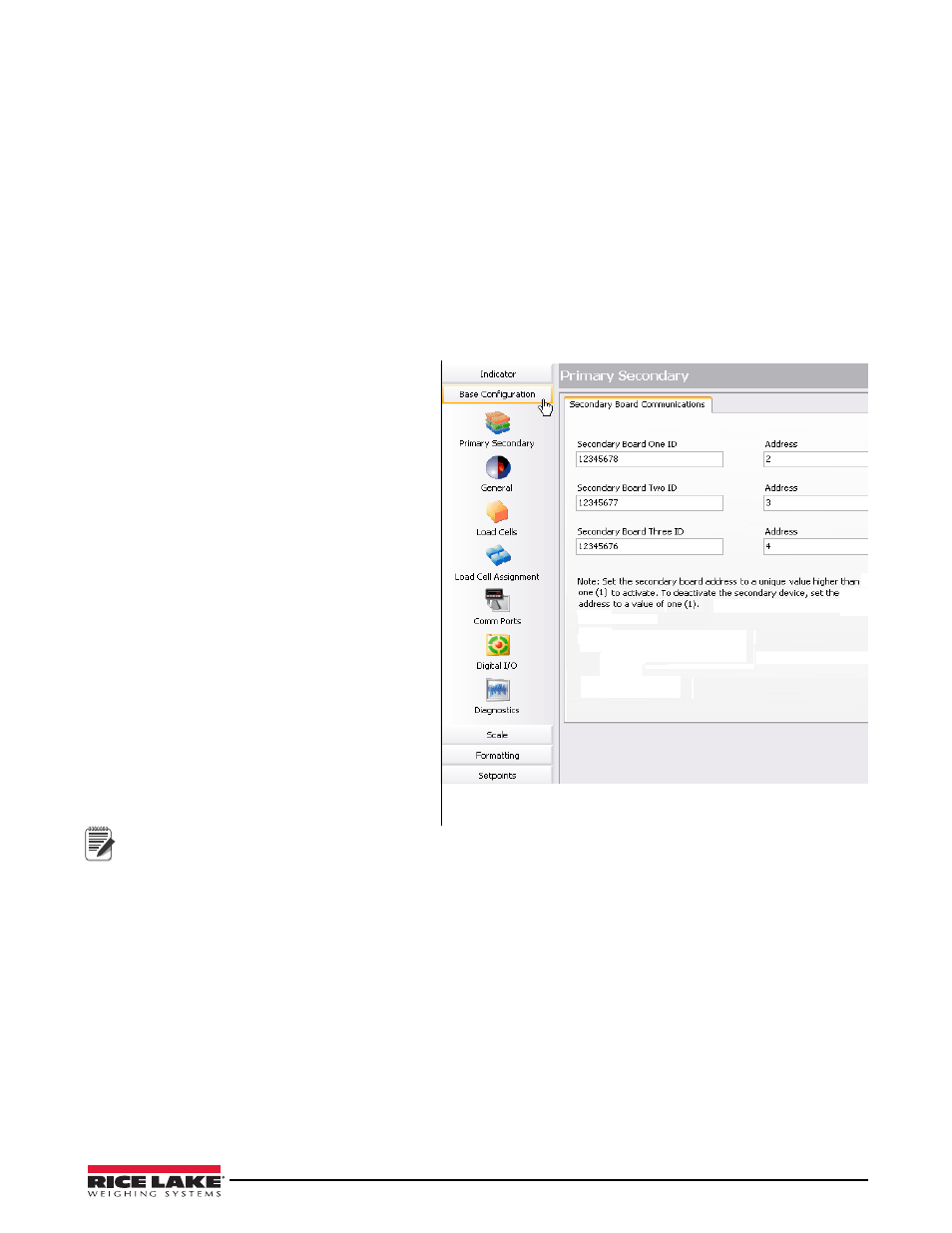
Primary/Secondary Configuration
1. From the Base Configuration list, on the left
pane, click
Primary Secondary
.
2. For each secondary device, enter the desired
eight-digit ID.
3. Set the address to a value other than 1 to
activate the device. Each secondary device
must have its own unique address.
To deactivate the secondary device, set
the address to 1 (use the address text boxes shown in Figure 3-17).
General Configuration
1. From the Base Configuration list, on the left pane, click
General
. Use the
Formatting
tab to modify the date
and time formats.
2. Use the
Sample Rate
tab to specify the sample rate (2.5HZ-500HZ).
Load Cell Configuration
The
Load Cells
section allows you to enter the capacity, sensitivity, name, serial number, zero value, and normaliza-
tion value for each load cell (up to 16).
1. From the left pane, click
Load Cells
.
2. From the listing of load cells, click on the one to be customized.
3. Using the text boxes, specify the capacity and sensitivity. Optionally, a load cell name and the load cell serial
number can be entered.
4. Zero and normalization values are set when the scale is calibrated, but can be customized by entering new
values in the text boxes.
5. Repeat Steps 1-4 for as many cells as are connected to the iQUBE
2
.
Figure 3-17. Rev III Base Configuration, Primary/Secondary
Communications
Note