1 assigning board addresses, Assigning board addresses – Rice Lake iQUBE2 Digital Diagnostic Junction Box User Manual
Page 17
Installation
13
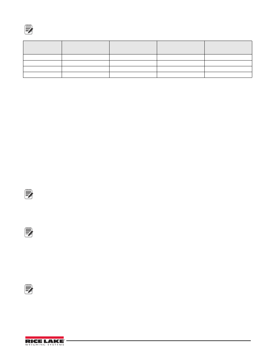
The cell numbering for secondary units follows the sequence of the load cell connector designations, with
connectors J1–J4 of the first secondary unit assigned cells 5–8, as shown in Table 2-11
2.7.1 Assigning Board Addresses
Once the primary and secondary unit ports are wired (see Figure 2-2), their addresses must be assigned. There are
two ways to assign the secondary board addresses in an iQUBE
2
system: manually (manual entry) or automatically
(push-button assignment).
Manual address assignments are done by manually entering the secondary board IDs and the desired addresses in
the Virtui
2
Configuration Utility (see Section 3.2.3 on page 26), Revolution III (see Section 3.3.1 on page 30), or
the 920i.
MS.AUTO
The MS.AUTO algorithm can be started via software using a terminal program and typing MS.AUTO or by press-
ing the
Auto Assign
softkey in the
Boards
menu of the 920i. Additionally, the following hardware implementation of
the MS.AUTO algorithm can be used when no HMI is connected or the HMI is not easily accessible.
1. Place the desired primary iQUBE
2
into setup mode by setting SW1 to CFG.
2. Remove power to the primary iQUBE
2
by unplugging the J6 connector from the CPU board.
3. Press and hold
S1
and return power to the CPU board by reconnecting J6.
4. Once J6 is reconnected, release
S1
to begin the MS.AUTO algorithm.
The green status LEDs for each channel will blink on all iQUBE
2
CPU boards in the system (primary and
secondary).
MS.AUTO places all
iQUBE
2
boards in the system in a suspended state in which they are unresponsive to any
commands. Once started, MS.AUTO can only be terminated by pressing the S1 switch, waiting for the algorithm
to time out (approximately 5 minutes) or powering down the units.
Push-Button Address Assignment
Once MS.AUTO has been started (all boards’ channel status LEDs are blinking), the addresses for the secondary
boards can be assigned.
If MS.AUTO has been set on the iQube
2
and it will be connected to a 920i, upload the data from the iQube
2
to the
920i. Ensure the master and secondary are configured, using the serial port menu go into the iQube screen and
connect to the iQube. Select upload to get data to 920i.
1. On the unit desired to be Secondary #1 (not the primary board), press and release the
S1
button. This registers
its ID with the primary unit which will then assign it an address. The channel status LEDs on this board will
stop blinking (the status LEDs for all other boards in the system will continue blinking).
2. Repeat Step 1 for Secondary Unit #2 and #3 (if necessary).
3. Once all secondary units have been assigned, press and release the
S1
button on the primary iQUBE
2
.
4. If using the hardware implementation method described above, store the assigned addresses into non-volatile
memory by setting SW1 to OFF on the primary iQUBE
2
.
For accessibility, in enclosures that contain more than one
iQUBE
2
board, the top board is typically the primary.
Manual Assignment with Virtui
2
Primary/secondary assignment is performed within the
Device Configuration
section of the Virtui
2
Configuration
Utility
.
Refer to Section 3.2.3 on page 26.
Manual Assignment with Revolution III
Primary/secondary assignment is performed within the
Base Configuration
section
.
Refer to Section 3.3.1.
Load Cell
Connector
Primary
iQUBE
2
Cell Numbers
Secondary
iQUBE
2
#1
Cell Numbers
Secondary
iQUBE
2
#2
Cell Numbers
Secondary
iQUBE
2
#3
Cell Numbers
J1
1
5
9
13
J2
2
6
10
14
J3
3
7
11
15
J4
4
8
12
16
Table 2-11. Cell Numbering for Multiple-Board System
Note
Note
Note
Note