3 920i–iqube2 menu configuration, 920i–iqube, 3 920i–iqube – Rice Lake iQUBE2 Digital Diagnostic Junction Box User Manual
Page 26: Menu configuration, Use the, Key to specify a parameter selection, Menu as shown in figure 3-5 to select the iqube
22
iQUBE
2
Installation Manual
3.1.3 920i–iQUBE
2
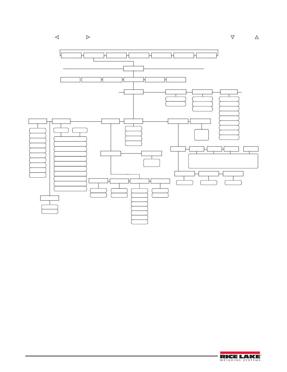
Menu Configuration
Use the
LEFT
( ) and
RIGHT
( ) navigation keys to move between menu selections. Use the
DOWN
( ) and
UP
( )
navigation keys to enter and exit menu selections. Use the
ENTER
key to specify a parameter selection.
Figure 3-5. 920i Serial Menu
1. If you have multiple boards, they need to be assigned. See Section 2.7.1 on page 12.
2. Navigate through the
Serial
menu as shown in Figure 3-5 to select the iQUBE
2
to begin setup.
SCALES
SERIAL
FEATURE
PFORMT
SETPTS
DIG I/O
VERS
PORT 4
CONFIG
IQ COM1
PROGIN
CMD
…
SCALE
IQUBE2
IND SC
ADDRESS
BAUD
EOLDLY
4
3
1
2
See
SCALES
Screen
DISPLAY
COMM SEL
IQOPTCOM
Same as
IQ COM1
BIT 1 … BIT 4
HOSTCTRL
CELHLTH
SETPNT
OFF
ZERO
TARE
NT/GRS
UNITS
PRINT
CLRCN
CLRTAR
IQ COM1
IQOPTCOM
5HZ
500HZ
2.5HZ
10HZ
15HZ
25HZ
100HZ
60HZ
30HZ
50HZ
A1
…
D4
A2
A3
A4
CAPACITY
SENSITV
ID
75000.00
3.000000
CELL#1
Same as A1
Number of cells depends on number of boards selected
(4 cells per board, 16 cells maximum)
(Board 1 = A, Board 2 = B, Board 3 = C, Board 4 = D)
232
422
485
RSPDLY
6
0-10
PORTTYPE
UPDATE
5HZ
2.5HZ
10HZ
15HZ
25HZ
100HZ
60HZ
30HZ
50HZ
SMPRAT
DIGIO
WARMUP
COMM
BOARDS
0
number
2
number
460800
450000
115200
230400
38400
9600
19200
57600
0
number
SCALES
CELLS