Rice Lake iQUBE2 Digital Diagnostic Junction Box User Manual
Page 29
Configuration
25
CONFIG Menu
1. Use the
CONFIG
menu to select the iQUBE
2
board and
cell configuration.
2. Use the
CELLS
submenu to enter load cell IDs, capaci-
ties, and factory sensitivity values (optional).
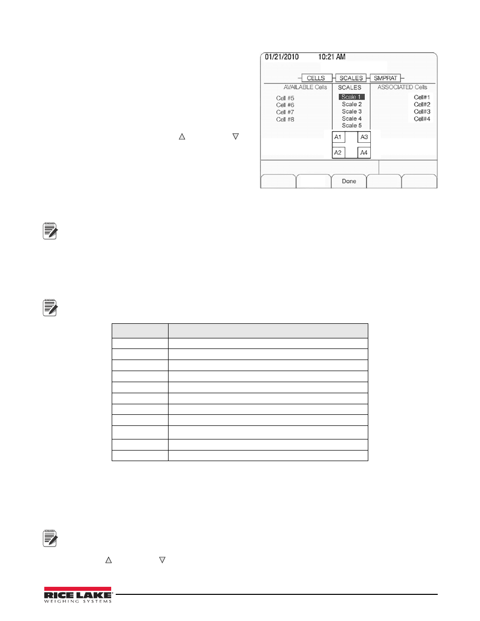
3. The Scale Setup display is divided into three areas:
•
Potential Scales
(center section): Highlight the scale
being configured, then use the
left
arrow key to move
to the
Available Scales
section.
•
Available Cells
(left section): Use this section to assign
cells to the system. Use the
UP
( ) and
DOWN
( )
keys to highlight the desired cell, then press the
Add
softkey to assign the cell.
•
Associated Cells
(right section): Lists cells that have
been assigned to the scale. Added cells will change
the visual representation of the scale base shown at
the bottom of the screen. Make sure the location of
the cells on the screen matches that of cells on the
actual scale to ensure diagnostic and trimming func-
tions will correctly work.
Scale 5 is the total scale. When it is highlighted, defined scales are available for summing.
4. Press
Done
to accept the configuration.
5. Continue through the
CONFIG
menu to set the sample rate, digital i/o, and communications parameters.
Associating Digital I/O
1. Use the DIGIO parameter to specify the function of each digital i/o bit. By default, Bits 1-4 are set to
OFF
.
Higher number bits (secondary boards) are set to cell health by default and cannot be changed.
Revolution III
should be used to fully configure the parameters shown in Table 3-2.
Setting COMM Parameters and Downloading Configuration
1. Use the COMM parameter to set the iQUBE
2
baud rate, end-of-line delay (0-255, in 0.1-second intervals),
and RS-485 address (not recommended for the 920i).
2. Connect to the 920i (see Section 3.1.1 on page 21).
3. Once the entire iQUBE
2
configuration is complete, press the
Download
softkey under the
Configuration
menu.
Serial configuration changes require downloading; however, changes made under the Scale menu are made in
real-time at the
iQUBE
2
.
4. Use the
UP
( ) and
DOWN
( ) keys to select
Download
iQUBE
2
configuration only
, then press
ENTER
.
Parameter
Description
OFF
The bit is not configured.
ZERO
Provides the same function as the ZERO front panel key.
TARE
Provides the same function as the TARE front panel key.
NT/GRS
Toggles between net/gross mode.
UNITS
Provides the same function as the UNITS front panel key.
Provides the same function as the PRINT front panel key.
CLRCN
Resets the consecutive number.
CLRTAR
Clears the current tare for the active scale.
SETPNT
Designates the bit as a free-running setpoint within the
iQUBE
2
.
CELHLTH
Assigns the cell health function.
HOSTCTRL
Gives control of the bit to the host.
Table 3-2. DIGIO parameter descriptions
Figure 3-6. Scale Setup Screen
Note
Note
Note