7 primary/secondary wiring and configuration, An iqube, System can consist of up to four iqube – Rice Lake iQUBE2 Digital Diagnostic Junction Box User Manual
Page 16: Boards; large enclosures allow up to three iqube, Board, Iqube
12
iQUBE
2
Installation Manual
2.7
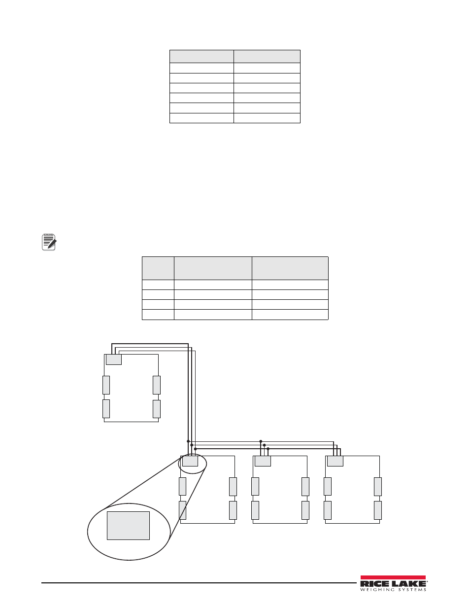
Primary/Secondary Wiring and Configuration
An iQUBE
2
system can consist of up to four iQUBE
2
boards, with up to four load cell channels wired to each
board. Standard enclosures can accommodate one or two iQUBE
2
boards; large enclosures allow up to three
iQUBE
2
boards. For control of a multi-board system, one iQUBE
2
board is assigned as the primary unit and the J12
connector (M/S port) is used to provide communication between the primary and up to three secondary units.
Figure 2-3 shows the primary-to-secondary wiring for multiple iQUBE
2
boards. Successive secondary units are
wired in parallel (A to A, B to B, GND to GND) to the J12 connector of each iQUBE
2
board.
The M/S port provides RS-485 communications at approximately 450 Kbps. This port is reserved for
communication between
iQUBE
2
boards. No other devices should be connected to this port.
Figure 2-3. Primary-to-Secondary Communications Wiring
J5 Pin
J5 Signal
1
+5V
2
GND
3
I/O 1
4
I/O 2
5
I/O 3
6
I/O 4
Table 2-10. J5 Pin Assignments (Digital I/O)
J12 Pin
Primary
iQUBE
2
Secondary
iQUBE
2
1
iQA
iQA
2
iQB
iQB
3
GND2
GND2
4
GND2
GND2
Table 2-1. J12 Primary/Secondary
Port
Note
GND2
GND2
iQB
iQA
J12
CELLS 1 – 4
1
2
3
4
GND2
GND2
iQB
iQA
J12
CELLS 5 – 8
5
6
7
8
GND2
GND2
iQB
iQA
J12
CELLS 9 – 12
9
10
11
12
GND2
GND2
iQB
iQA
J12
CELLS 13 – 16
13
14
15
16
Primary iQUBE²
Secondary
iQUBE² #1
Secondary
iQUBE² #2
Secondary
iQUBE² #3
GND2
GND2
iQB
iQA
J12