2 info, 3 device configuration, 4 communications – Rice Lake iQUBE2 Digital Diagnostic Junction Box User Manual
Page 31: Info, Device configuration, Communications
Configuration
27
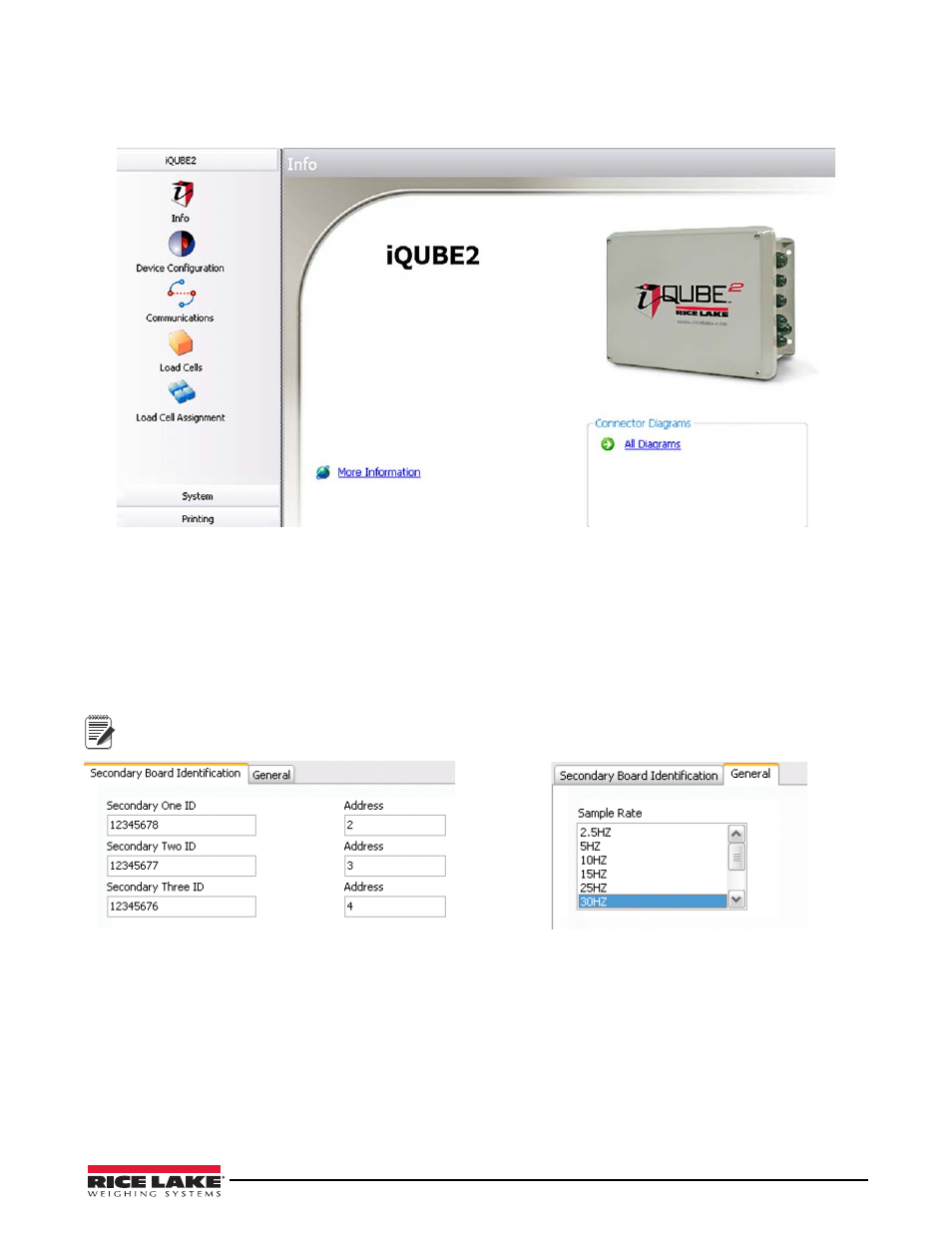
3.2.2 Info
This is the default section that is displayed when a configuration file is opened for editing. A graphic of the
iQUBE
2
,
links to more information, and links to connector diagrams are displayed in this section.
Figure 3-8.
iQUBE
2
Section, Info
3.2.3 Device Configuration
Device Configuration allows you to customize secondary device identification and sample rate.
1. From the left pane, click
Device Configuration
. Select the
Secondary Board Identification
tab.
2. For each secondary device, enter the desired ID (located on the CPU board; see Figure 3-1).
3. Set the address to a value other than 1 to activate the device. Each secondary device must have its own unique
address between 2-254.
4. Use the
General
tab to specify the sample rate.
To deactivate the secondary device, set the address to 1.
3.2.4 Communications
This section allows you to specify communications settings and stream format for the alternate communications
port.
1. From the left pane, click
Communications
. Select the
General
tab.
2. Using the drop-down menus, specify the baud rate, terminator, end of line delay, prefix character, data bits/
parity, echo, RS-485 address, postfix character, and stop bits as desired.
3. Select the
Stream Format
tab.
4. Use the buttons and to insert tokens into the stream output (streaming must be enabled in the
Scales
section).
Organize it into the desired order.
Note
Figure 3-9. Secondary Board Identification Tab
Figure 3-10. General Tab