4 load cells – Rice Lake iQUBE2 Digital Diagnostic Junction Box User Manual
Page 11
Installation
7
2.4
Load Cells
When wiring load cells, cells wired to iQUBE
2
connectors J1–J4 are assigned by default as channels 1–4 (5–8, 9–
12, 13–16 for secondary units). Be aware that graphic representations of the weighing platform shown when con-
figuring the scale assume particular locations for each load cell, based on the iQUBE
2
connector used. Load cells
can be renamed during configuration.
While load cells can be wired to any connector on the iQUBE
2
connector board, platforms defined as using
“paired” sections (including most truck scale applications) must correctly associate these pairs to ensure valid cali-
bration and diagnostic functions.
Load Cell Wiring
To attach load cell cables to the iQUBE
2
board, route the cables through the cord grips on the load cell connector
end of the enclosure.
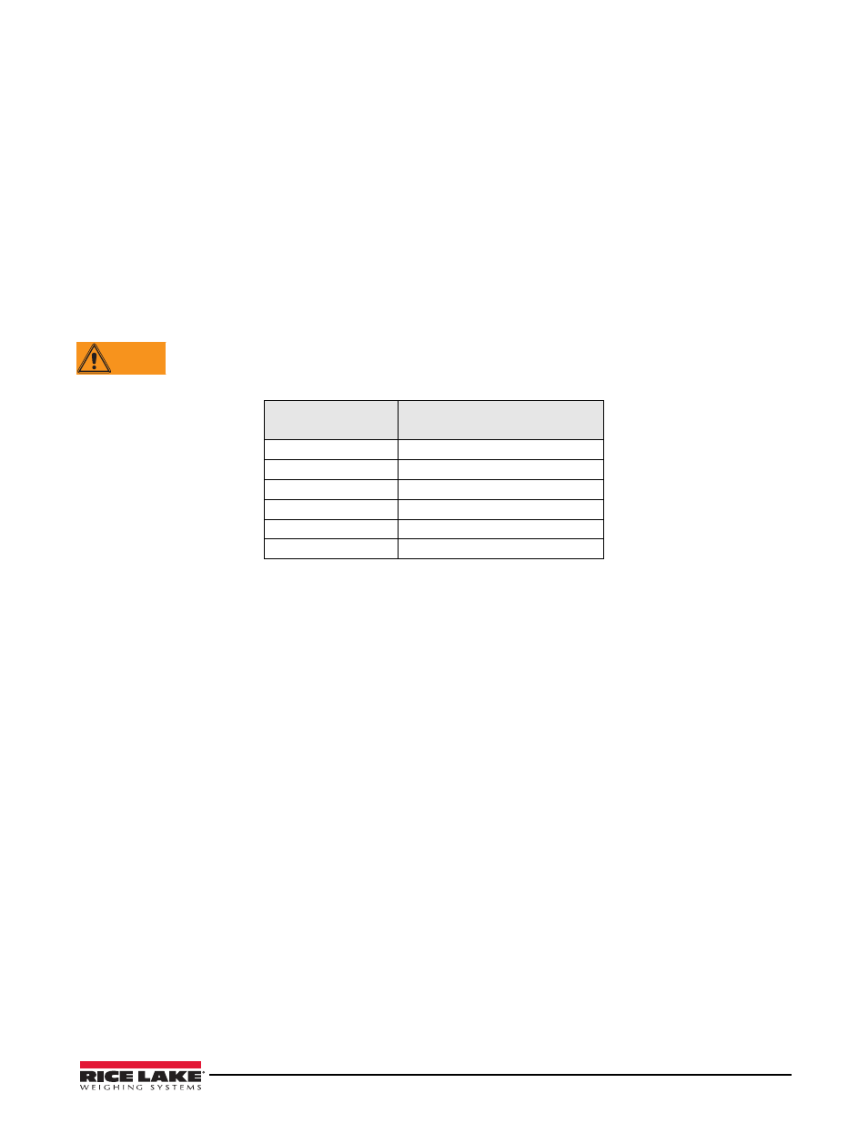
Strip 1/4-inch of insulation from the ends of the load cell wires and install wires into the connectors. Wire load cell
cables as shown in Table 2-1.
Pins 5 and 6 provide connections for load cells that provide TEDS (Transducer Electronic Data Sheet)
information.
DO NOT CONNECT SENSE WIRES TO THE TD TERMINALS
When connections are complete, use cable ties and mounts to secure load cell cables to the enclosure’s interior.
Load Cell Connector
Pins (J1–J4)
Function
1
+SIG
2
–SIG
3
+EXC
4
–EXC
5
+TD (TEDS)
6
–TD (TEDS)
Table 2-1. Load Cell Connector Pin Assignments
WARNING