6 digital i/o – Rice Lake iQUBE2 Digital Diagnostic Junction Box User Manual
Page 15
Installation
11
2.6
Digital I/O
Each iQUBE
2
board provides four channels of digital I/O.
Digital inputs can be set to provide many indicator functions, including four keys (
Zero
,
Tare
,
Units
,
Mode
) plus cell
health, and setpoints (see Table 5-10 on page 45 for a complete listing). The four digital inputs/outputs on the pri-
mary CPU are configurable; any secondary CPU board’s I/O will be used for cell health only.
The fastest I/O reaction times are achieved when the iQUBE
2
controls its own free-running setpoints using its own
local I/O (2 milliseconds). If preacts are required, the 920i should be used as the controller for its own I/O.
RLWS does not recommend the use of iQUBE
2
(local) I/O with 920i controlled setpoints using the preact functions
as variances in the reaction time in serially controlled I/O can dramatically affect the preact algorithm.
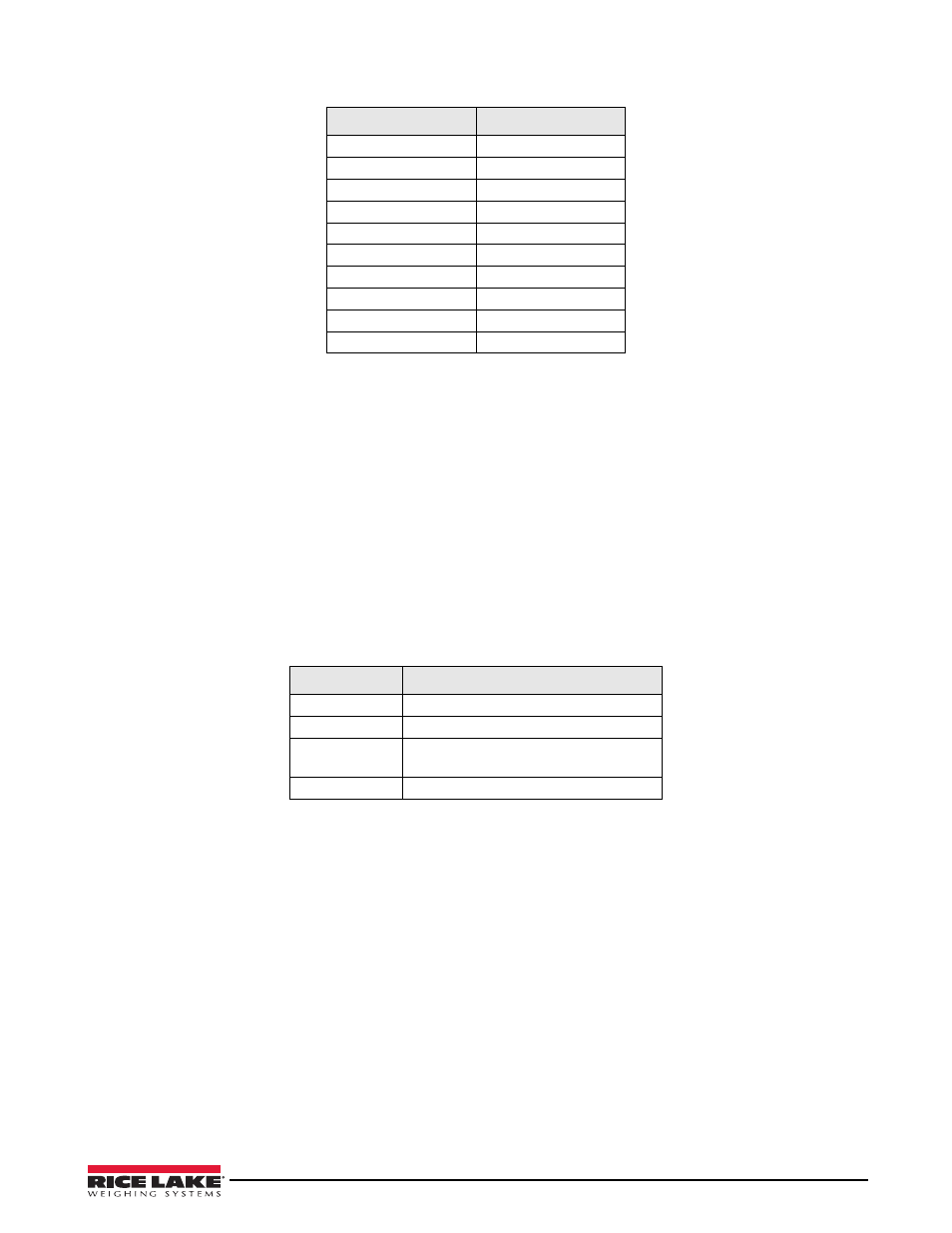
Cell Health
The iQUBE
2
CPU board provides bi-color cell status LEDs next to each load cell connector. These LEDs indicate
the status of connected load cells.
Digital inputs are active low (0 VDC), inactive high (5 VDC). Digital I/O are active/low if the CPU board’s LED
color is green.
Digital outputs are typically used to control relays that drive other equipment. Outputs are designed to sink, rather
than source, switching current.
Each output is a normally open collector circuit, capable of sinking 25 mA when active. Digital outputs are wired
to switch relays when the digital output is active (low, 0 VDC) with reference to a 5 VDC supply.
Table 2-10 shows the pin assignments for connector J5.
Data Rate
Approx. Range
54 Mbps
65 feet
48 Mbps
80 feet
36 Mbps
115 feet
24 Mbps
140 feet
18 Mbps
170 feet
11 Mbps
180 feet
9 Mbps
190 feet
5.5 Mbps
215 feet
3 Mbps
260 feet
1 Mbps
330 feet
Table 2-8. Approximate 802.11g data rate/range
LED Color
Meaning
Green
Load cell is good
Red
Load cell error
Red/Green
Flashing
Consistent error being cleared by host
Off
Disabled/load cell not assigned to a scale
Table 2-9. LED Status Indications