6 digital inputs, 7 relay contact outputs, 6 digital inputs 9.7 relay contact outputs – Rice Lake 320IS Plus Intrinsically Safe Digital Weight Indicator - Installation Manual User Manual
Page 83
320IS Plus Installation Manual - Appendix B
77
9.6
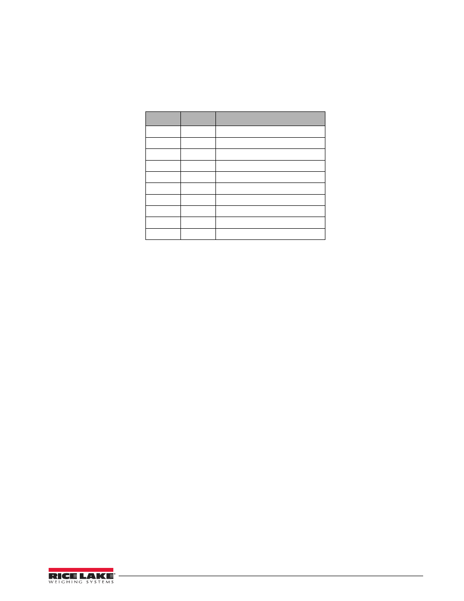
Digital Inputs
The
I/O Module
has four digital inputs that can be used to control pre-defined operations in the indicator.
Table 9-9 outlines the various functions for the digital inputs.
Digital inputs are available on connector CN4 (see Figure 9-1 on page 73). All inputs are individually isolated
via optocouplers. Table 9-9 outlines the pin connections for CN4.
The digital inputs are designed to receive 0-24V/TTL signals on the incoming lines. Care should be taken to
apply the right DC polarity. Pins 9 and 10 (+5V and DGND) can be used to supply power to the digital inputs.
Maximum current draw should not exceed 0.25A.
See the applicable indicator installation manual for information on checking current digital input states.
9.7
Relay Contact Outputs
The
I/O Module
features four relay contact outputs, which default to open. This allows switching of maximum
+30VDC, 5A or 250VAC, 5A for each of the four digital channels.
The relay contact outputs are controlled by user-configurable setpoints. The setpoint values and operating
parameters can be defined in the SETPNT menu of the host indicator. See the indicator installation manual for
information on configuring setpoints.
Table 9-10 show pin connections for CN5 of the
I/O Module
board.
Pin
State
Description
1
Hi
Digital Input 1 (+V)
2
Low
Ground 1 (–V)
3
Hi
Digital Input 2 (+V)
4
Low
Ground 2 (–V)
5
Hi
Digital Input 3 (+V)
6
Low
Ground 3 (–V)
7
Hi
Digital Input 4 (+V)
8
Low
Ground 4 (–V)
9
Hi
+5V
10
Low
DGND
Table 9-9. CN4 Connections