4 foil load cell cable connection, Foil load cell cable connection, Figure 2-4 – Rice Lake 320IS Plus Intrinsically Safe Digital Weight Indicator - Installation Manual User Manual
Page 20
14
320IS Plus Installation Manual
6. Thread the load cell cable through the domed cap, then through the reducing gland/metal sleeve
assembly.
7. Lower the reducing gland assembly so that the end of the metal sleeve is at the edge of the insulation and
fold the braid back over the sleeve (see Figure 2-2). Trim if necessary.
8. Thread the cable through the cord grip stem.
Chassis ground is made through the braid compressed between the metal sleeve and the cord grip stem.
9. Lower the domed cap onto the cord grip stem and tighten until a small swelling of the rubber of the
reducing gland appears between the dome cap and the cable (see Figure 2-3).
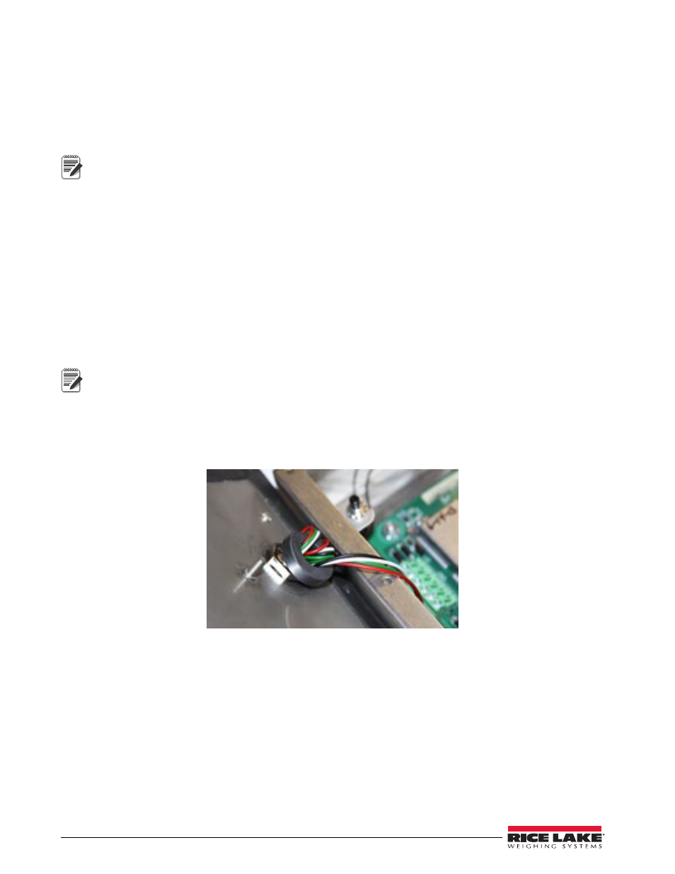
10. Thread the load cell cable through the ferrite core, from the parts kit, twice. Keep the ferrite core as close
to the backplate as possible (see Figure 2-4).
If Using 4 Wire Load Cell Cable
1. Carefully remove 8" of outside insulation and 7 1/2" of braid from the load cell cable.
2. Remove the metal domed cap and reducing gland from cord grip, place them on a work surface.
3. Thread the load cell cable through the domed cap, then through the reducing gland/metal sleeve
assembly.
4. Lower the reducing gland assembly so that the end of the metal sleeve is at the edge of the insulation and
fold the braid back over the sleeve (see Figure 2-2). Trim if necessary.
5. Thread the cable through the cord grip stem.
Chassis ground is made through the braid compressed between the metal sleeve and the cord grip stem.
6. Lower the domed cap onto the cord grip stem and tighten until a small swelling of the rubber of the
reducing gland appears between the domed cap and the cable (see Figure 2-3).
7. Thread the load cell cable through the ferrite core, from the parts kit, twice. Keep the ferrite core as close
to the backplate as possible (see Figure 2-4).
Figure 2-4. Ferrite Core Wire Wrap
2.4.4
Foil Load Cell Cable Connection
Use the following procedure for connecting foil load cell cable:
1. Carefully remove 8" of insulation and 7 1/2" of foil from cable.
2. Remove domed cap, reducing gland and metal sleeve from cord grip and place them on the cable (see
3. Thread the load cell cable through the domed cap, then through the reducing gland metal sleeve
assembly.
4. Lower reducing gland metal sleeve assembly to edge of insulation and wrap foil over metal sleeve of
reducing gland leaving the silver side out.
5. Thread the cable through the cord grip stem.
Note
Note