1 ac wiring/installation, 2 edp and printer ports, 3 rs-232 communications – Rice Lake 320IS Plus Intrinsically Safe Digital Weight Indicator - Installation Manual User Manual
Page 80: 4 rs-485 communications, 5 rs-422 communications, Ac wiring/installation, Edp and printer ports, Rs-232 communications, Rs-485 communications, Rs-422 communications
74
320IS Plus Installation Manual
9.3.1
AC Wiring/Installation
The
I/O Module
is to be permanently mounted with a readily accessible disconnect device incorporated in the
building installation wiring. All wiring is to be done in accordance with the National Electric Code (NEC).
9.3.2
EDP and Printer Ports
The indicator communicates with external devices through the
I/O Module
located in a remote location. The I/O
board serves as a gateway with several types of communication interfaces (RS-232, RS-422, RS-485, and 20mA
current loop). The following sections explain how to install and configure the communication interfaces to
establish serial communications with peripheral devices.
9.3.3
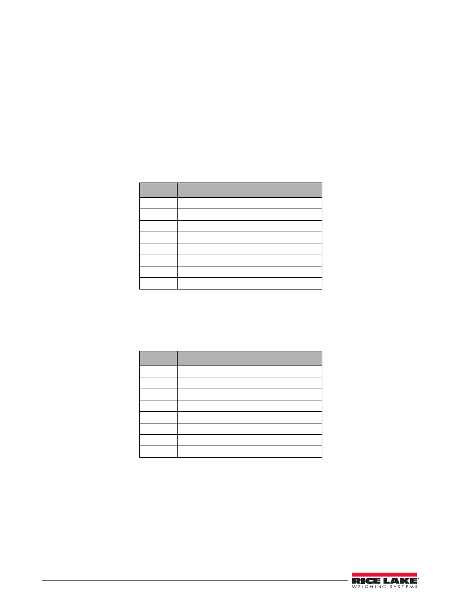
RS-232 Communications
To attach a PC or other device to the
I/O Module
’s RS-232 ports, select RS-232 standard in the indicator SERIAL
menu for the appropriate port (EDP and/or printer). EDP and printer ports should be configured separately. See
Table 9-3 below for information on connecting RS-232 communications.
9.3.4
RS-485 Communications
To attach a PC or other device to the
I/O Module
’s RS-485 ports, select RS-485 standard in the indicator SERIAL
menu for the desired port (EDP and/or printer). EDP and printer ports should be configured separately. See
Table 9-4 below for information on connecting RS-485.
9.3.5
RS-422 Communications
To attach a PC or other device to the
I/O Module
’s RS-422 ports, select RS-422 standard in the indicator SERIAL
menu for the desired port (EDP and/or printer). EDP and printer ports should be configured separately. See
Table 9-5 for information on connecting RS-422 communications.
Pin
Description (Sign)
1
Signal Ground (GND)
2
—
3
—
4
—
5
Receive Data (RXD)
6
—
7
—
8
Transmit Data (TXD)
Table 9-3. RS-232 Connections (CN2 and CN3)
Pin
Description (Sign)
1
Signal Ground (GND)
2
—
3
—
4
—
5
—
6
—
7
RS-485 line (A)
8
RS-485 line (B)
Table 9-4. RS-485 Connections (CN2 and CN3)