Rice Lake 320IS Plus Intrinsically Safe Digital Weight Indicator - Installation Manual User Manual
Page 57
320IS Plus Installation Manual - EDP Commands
51
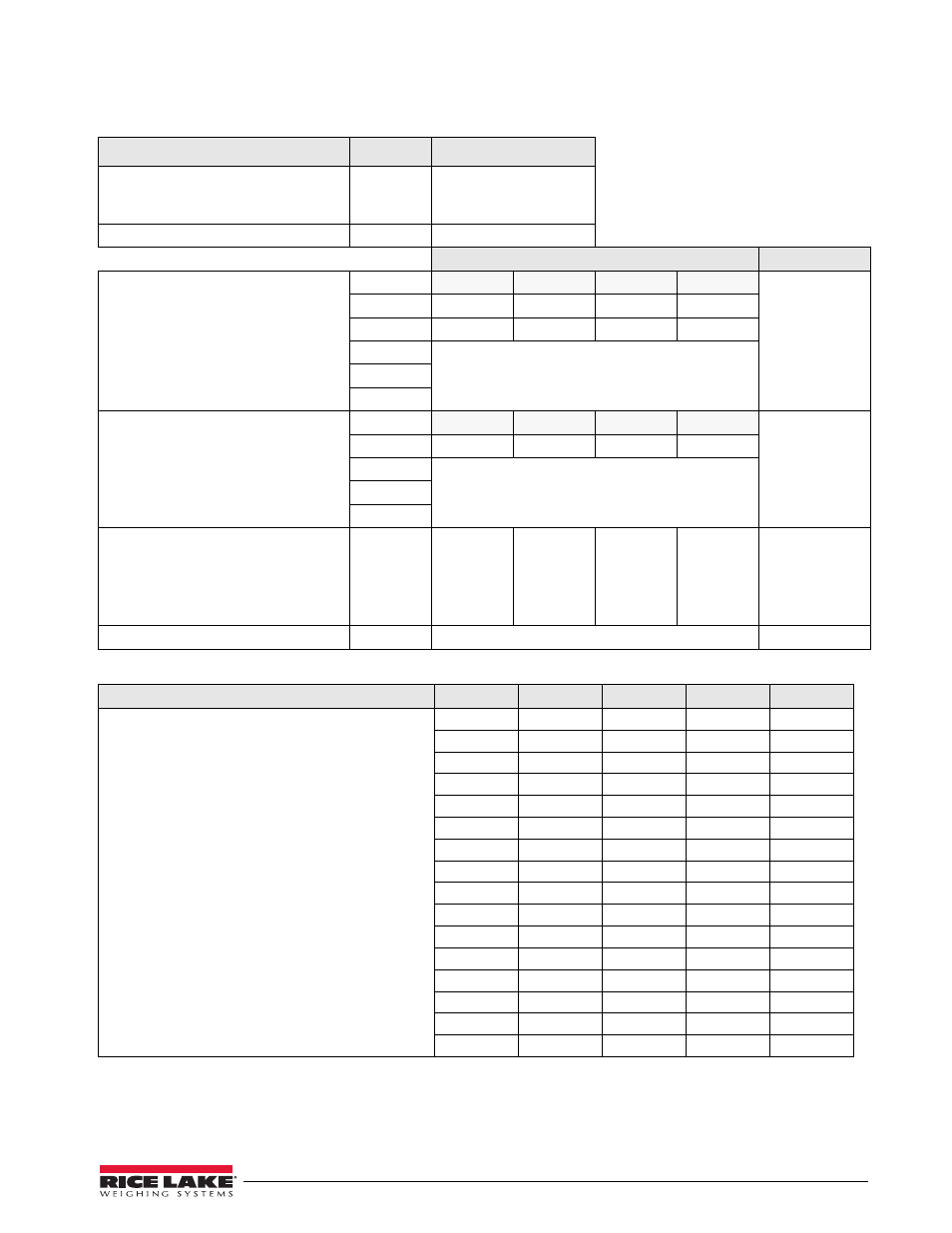
Table 5-15. BATSTATUS Command Structure
Table 5-16. ASCII Translation Table for BATSTATUS Data
Batch Status Data
Byte
Values
Batch Status
0
“S” = stopped
“R” = running
“P” = paused
Current Batch Step
1 – 2
00 – 8
Low Order Bit Assignments for Bytes 3 – 12
ASCII Values
Continuous Setpoint Status
Low order bits of bytes 3–4 are set on
to indicate continuous setpoints for
which conditions are being met. Bits are
assigned to setpoint numbers as shown
at right.
3 – 7
Bit 3
Bit 2
Bit 1
Bit 0
@@@@@ –
OOOOO
3
SP 1
SP 2
SP 3
SP 4
4
SP 5
SP 6
SP 7
SP 8
5
6
7
Digital Output Status
Low order bits of bytes 8–9 are set on
to indicate active digital outputs. Bits
are assigned to digital outputs as
shown at right.
8 – 11
Bit 3
Bit 2
Bit 1
Bit 0
@@@@ – OOOO
8
DIGOUT 1
DIGOUT 2
DIGOUT 3
DIGOUT 4
9
N/A
10
11
Digital Input / Alarm Status
Low order bits of byte 12 are set on to
indicate active digital inputs and
setpoint alarm status. Bits are assigned
as shown at right.
12
DIGIN 1
DIGIN 2
DIGIN 3
DIGIN 4
@ – O
Carriage Return
13
N/A
(CR)
Translating ASCII Status Data
ASCII Value
Bit 3
Bit 2
Bit 1
Bit 0
Use the table at right to evaluate the ASCII character
output for bytes 3 – 12 and determine which of the
low-order bitts are set on.
For example, if the digital output status returned in
bytes 8 – 11 is C, the table at right can be used with
the bit assignments described above to determine
that digital outputs 2 and 1 are active:
• A (byte 8) indicates that DIGOUT 4 (bit 0) is on
• C (byte 9) indicates that DIGOUTs 0 and 1 (bit 1
and 0) are on
• @@ indicates that bytes 10 and 11 are not used
@
0
0
0
0
A
0
0
0
1
B
0
0
1
0
C
0
0
1
1
D
0
1
0
0
E
0
1
0
1
F
0
1
1
0
G
0
1
1
1
H
1
0
0
0
I
1
0
0
1
J
1
0
1
0
K
1
0
1
1
L
1
1
0
0
M
1
1
0
1
N
1
1
1
0
O
1
1
1
1