6 20ma current loop, 4 fiber optics assembly, 20ma current loop – Rice Lake 320IS Plus Intrinsically Safe Digital Weight Indicator - Installation Manual User Manual
Page 81
320IS Plus Installation Manual - Appendix B
75
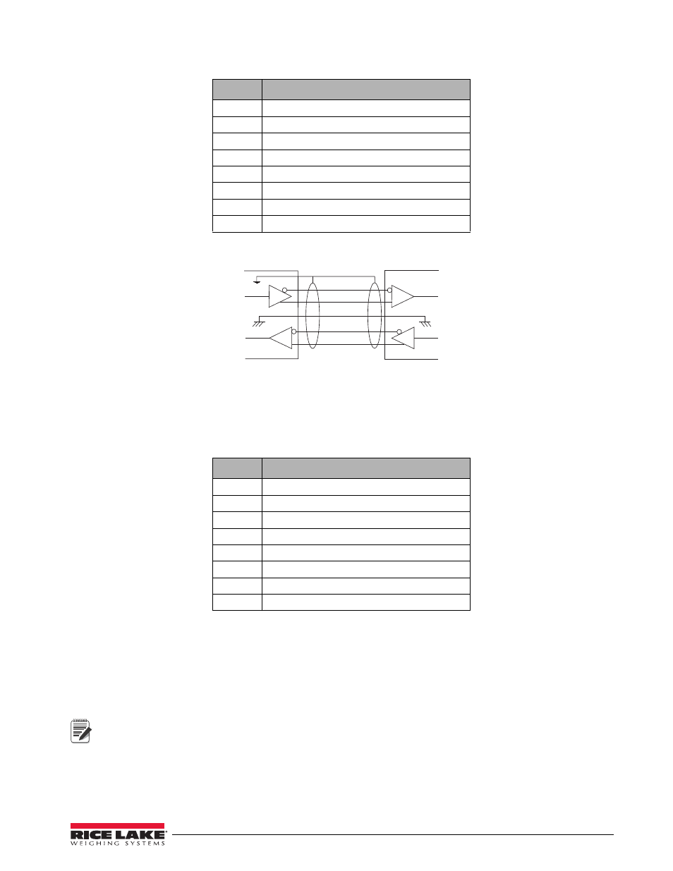
Figure 9-3. Typical RS-422 Wiring Paths
9.3.6
20mA Current Loop
To attach a PC or other device to the
I/O Module
’s 20mA ports, select current loop (CRLOOP) standard in the
indicator SERIAL menu for the desired port (EDP and/or printer). EDP and printer ports should be configured
separately. See Table 9-6 below for information on connecting 20mA current loop.
9.4
Fiber Optics Assembly
The
I/O Module
is equipped with duplex fiber optic ports for communicating with other devices located in the
safe or hazardous area. It provides electrical isolation and eliminates the use of I/O barriers commonly used in
intrinsically safe systems. The fiber optic wires are plastic; no polishing or further preparation is required. See
Figure 9-1 on page 73 for the location of the fiber optic ports on the
I/O Module
main board.
The fiber optic connections between the indicator and the
I/O Module
need to be cross-linked.
The optical output of the indicator should be attached to the input of the
I/O Module
, and the indicator’s
input to the module’s output.
Use the following steps for assembling the fiber optics connectors of the
I/O Module
:
1. Cut off the ends of the fiber optic cable with a single-edge razor blade or sharp knife. Try to obtain a
precise 90º angle.
Pin
Description (Sign)
1
Signal Ground (GND)
2
—
3
—
4
—
5
RS-422 input (R+)
6
RS-422 input (R-)
7
RS-422 output (T+)
8
RS-422 output (T-)
Table 9-5. RS-422 Connections (CN2 and CN3)
Pin
Description (Sign)
1
Signal Ground (GND)
2
Isolated Ground (GNDx)
3
Receive Data (RCL) Passive
4
Transmit Data (TCL) Active
5
—
6
—
7
—
8
—
Table 9-6. 20mA Current Loop Connections (CN2 and CN3)
I/O Modul e
8
7
1
6
5
Note