Rice Lake 320IS Plus Intrinsically Safe Digital Weight Indicator - Installation Manual User Manual
Page 45
320IS Plus Installation Manual - Configuration
39
installed and the analog output is being used, configure all other indicator functions and calibrate the indicator
(see See Section 4.0 on page 41) before configuring the analog output. See Section 8.7 on page 69 for analog
output calibration procedures.
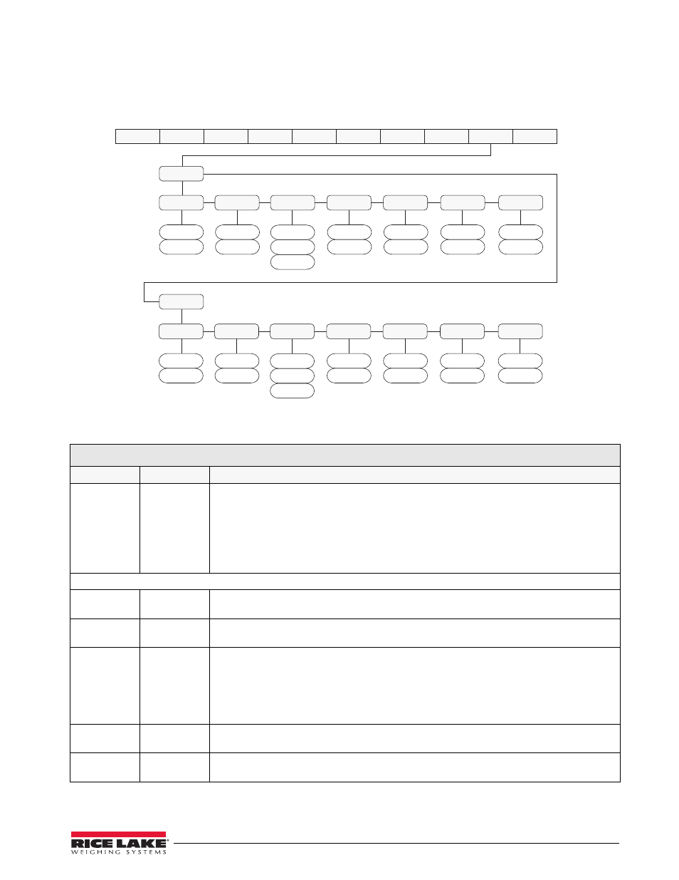
Figure 3-13. Analog Output Menu
ALG OUT Menu
Parameter
Choices
Description
ALOUT1
ALOUT2
SOURCE
OFFSET
ERRACT
MIN
MAX
TWZERO
TWSPAN
Specifies settings for source, offset, error action, minimum, maximum, tweak zero and tweak
span value used by analog output 1.
Level 2 submenus
SOURCE
GROSS
NET
Specifies the source tracked by the analog output.
OFFSET
0%
20%
Zero offset. Selects whether the analog output supplies voltage (0-5 V, ±5 V, ±10 V) or current
(4–20 mA) output. Select 0% for 0-5 V, ±5 V, ±10 V output, 20% for 4–20 mA output.
ERRACT
FULLSC
HOLD
ZEROSC
Error action — Specifies how the analog output responds to system error conditions.
Possible values are:
FULLSC
Set to full value
HOLD:
Hold current value
ZEROSC: Set to zero value
MIN
000000
number
Specifies the minimum weight value tracked by the analog output. Specify a weight value (in
primary units) in the range 000000–999 990.
MAX
010000
number
Specifies the maximum weight value tracked by the analog output. Specify a weight value (in
primary units) in the range 0–999 990.
Table 3-9. Analog Output Menu Parameters
SOURCE
GROSS
0%
20%
OFFSET
ERRACT
FULLSC
HOLD
000000
number
MI N
10000
number
MAX
TWZERO
NET
TWSPAN
ZEROSC
ALOUT1
0
number
65300
number
ALOUT2
XXXXXXX
XXXXXXX
XXXXXXX
XXXXXXX
VERS
ALGOUT
DIG IN
PROGRM PFORMT
SERIAL
CALIBR
CONFIG FORMAT
XXXXXXX
SETPNT
SOURCE
GROSS
0%
20%
OFFSET
ERRACT
FULLSC
HOLD
000000
number
MI N
10000
number
MAX
TWZERO
NET
TWSPAN
ZEROSC
0
number
65300
number