5 load cells, Load cells – Rice Lake 320IS Plus Intrinsically Safe Digital Weight Indicator - Installation Manual User Manual
Page 21
320IS Plus Installation Manual - Installation
15
Chassis ground is made through the foil compressed between the metal sleeve and the cord grip stem.
6. Lower the domed cap onto cord grip stem.
7. Tighten until a small swelling of the rubber between the domed cap and the cable builds (see Figure 2-3).
8. Thread wires through ferrite core two times. Keep the ferrite as close to the backplate as possible (see
9. Wire cable to connector CN3.
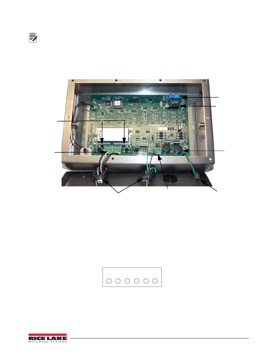
Figure 2-5. Cable Connections
2.4.5
Load Cells
To attach cable from a load cell or junction box, use six-position connector in parts kit. See Section 2.4 on
page 11 for information on cabling through metal cord grips.
Wire the load cell cable from the load cell or junction box to connector CN3 as shown in Figure 2-6. If using
6-wire load cell cable (with sense wires), remove jumpers J1 and J2 before installing connector CN3. For
four-wire installation, leave jumpers J1 and J2 on.
When connections are complete, reinstall connector CN3 on the board and use two cable ties to secure the load
cell cable to the inside of the enclosure.
Figure 2-6. CN3 Load Cell Connections
Note
Load cell
connector
Power cable connector
Green = +Voltage
Brown = Return
125mA fully –
encapsulated
fuses
F1 & F2
Blue opptical
output
Black optical
input
Ferrite cores
C h a s s i s
ground
Sense jumpers
J1 & J2
1 2 3 4 5 6
CN3
-Excitation
-Sense
-Signal
+Signal
+Sense
+Excitation