3 hazardous area installation of the 320is plus, 1 power supply to indicator, Power supply to indicator – Rice Lake 320IS Plus Intrinsically Safe Digital Weight Indicator - Installation Manual User Manual
Page 16
10
320IS Plus Installation Manual
2.3
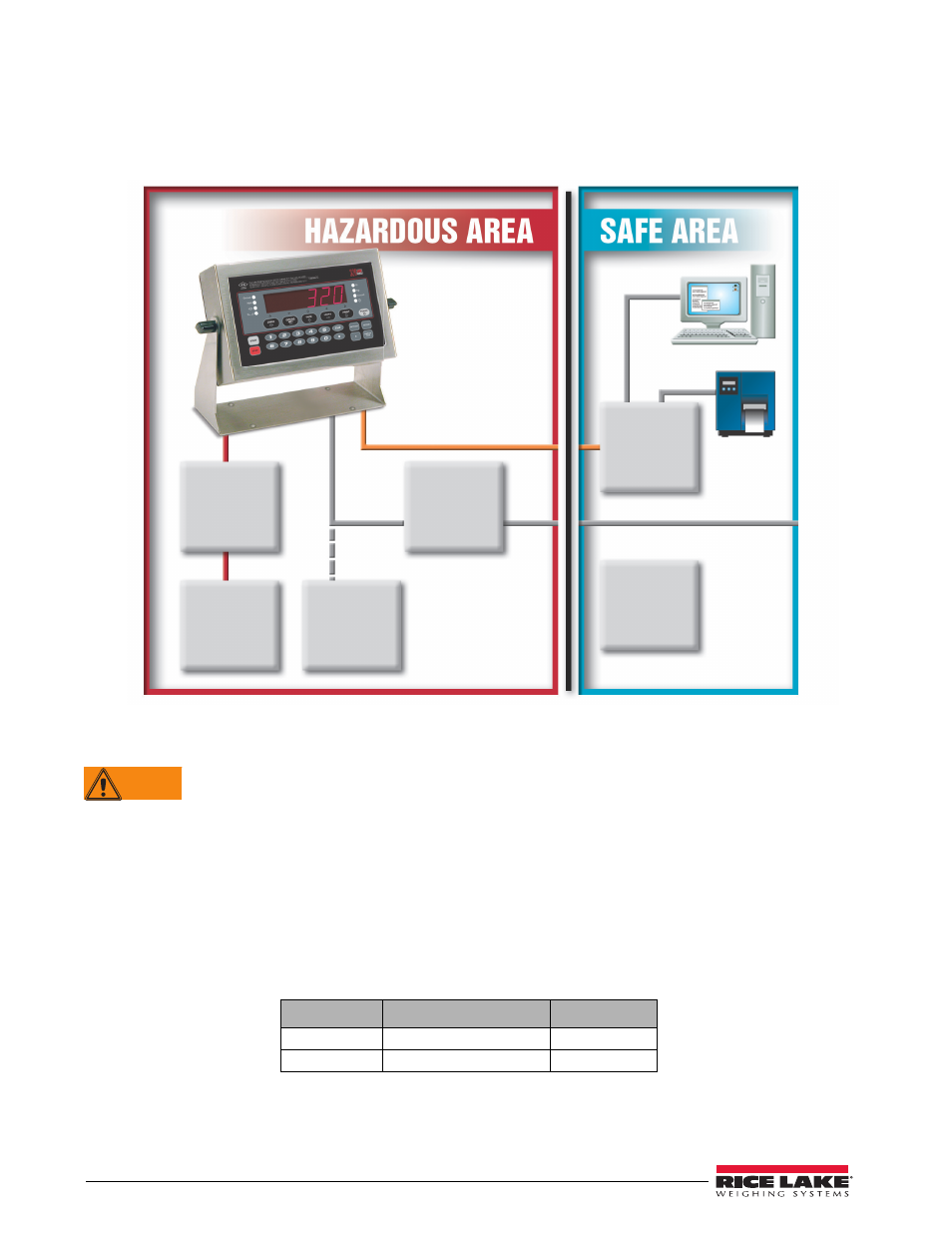
Hazardous Area Installation of the 320IS Plus
The following information is provided to help the installer with the correct installation of the
320IS Plus
system.
See Figure 2-1 below for a diagram of a typical intrinsically safe system.
Figure 2-1. Intrinsically Safe System Diagram
2.3.1
Power Supply to Indicator
Do not, under any circumstances, connect or disconnect the DC wire from the indicator while the AC
power is applied to the power supply. This will cause the power supply fuse to blow.
The indicator should be powered by an FM-approved Rice Lake power supply or alternatively from an external
battery pack. The power requirements of the
320IS Plus
are as follows:
•
Minimum input voltage: 5.8 V
•
Maximum input voltage: 7.9 V
•
Peak current consumption: 190 mA
•
Average input current (with four load cells): 140 mA
The DC power cable should be attached to connector CN1 (see Table 2-1). Care must be taken to wire CN1 with
the correct DC polarity. See Section 2.4 on page 11 for information on cabling through metal cord grips.
CN1 Pin
Function
Wire Color
1
+ Voltage (5.8 – 7.9 V)
Green
2
Ground (V–, Common)
Brown
Table 2-1. DC Power Supply Connections
Junction
Box
(Optional)
AC Power
Supply
(Intrinsically
Safe Output)
FM-Approved
Load Cells
(up to 4–350Ω)
Battery
(Optional)
I/O Module
(Optional)
Battery
Charger
(Optional)
Load Cell
Input
Fiber Optic
VDC
115/230VAC
WARNING