Junction box cover, cable cover, and end cap – Dynojet 250i: Pit Installation Guide User Manual
Page 77
I N S T A L L A T I O N
Junction Box Cover, Cable Cover, and End Cap
Version 4
In Ground Model 200iP/250iP Motorcycle Dynamometer Installation Guide
2-55
. . . . . . . . . . . . . . . . . . . . . . . . . . . . . . . . . . .
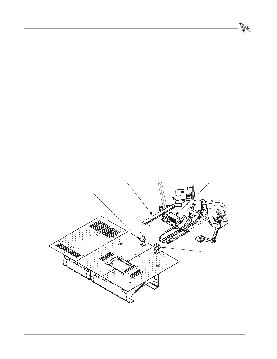
JUNCTION BOX COVER, CABLE COVER, AND END CAP
Before installing the junction box cover, cable cover, and end cap be sure to route all
of your cables.
You will need the following parts:
• 21228517
Cable Routing Cover
• 21228519
Cable Channel End Cap
• 21228521
Junction Box Cover
• 21626902
Cable Cover, Pit to Junction Box
• 36540643
Screw, 8-32 x 3/8", Pan-Head, Phil (13)
1
Secure the junction box cover to the junction box using two 8-32 x 3/8-inch pan-
head screws.
2
Secure the end cap to the pit cover using two 8-32 x 3/8-inch pan-head screws.
3
Secure the cable cover to the end cap using four 8-32 x 3/8-inch pan-head screws.
4
Secure the cable cover to the junction box cover using one 8-32 x 3/8-inch pan-
head screw.
Note: Verify the cables are placed inside the cable cover.
5
Secure the cable routing cover to the right side pit cover using four
8-32 x 3/8-inch pan-head screws.
Figure 2-49: Install the Junction Box Cover, End Cap, and Cable Cover
PD178
end cap
cable cover
junction box cover
cable routing cover