Unpacking the eddy current brake – Dynojet 250i: Pit Installation Guide User Manual
Page 33
I N S T A L L A T I O N
Eddy Current Brake
Version 4
In Ground Model 200iP/250iP Motorcycle Dynamometer Installation Guide
2-11
U
NPACKING
THE
E
DDY
C
URRENT
B
RAKE
1
Remove the four bolts securing the brake to the crate.
2
Remove the retarder connector plates, if present.
3
Determine if the brake is to be mounted on the left or right side of your dyno.
Note: This installation has been designed for the eddy current brake to be
installed on the left side of the dyno. Contact Dynojet for information regarding
installation on the right.
Make the following adjustments to the eddy current brake only if you want to
mount the brake on the opposite side of the dyno that it is currently set up for.
• Move the coupler and key to the other side of the brake.
To remove the key, use a punch and a hammer to apply pressure in the
direction of the arrows shown in Figure 2-6.
• The retarder connector plates (removed in step 2) will need to be moved to
the other side of the brake once the brake is installed in the pit.
• Move the temperature sensor to the other side of the brake.
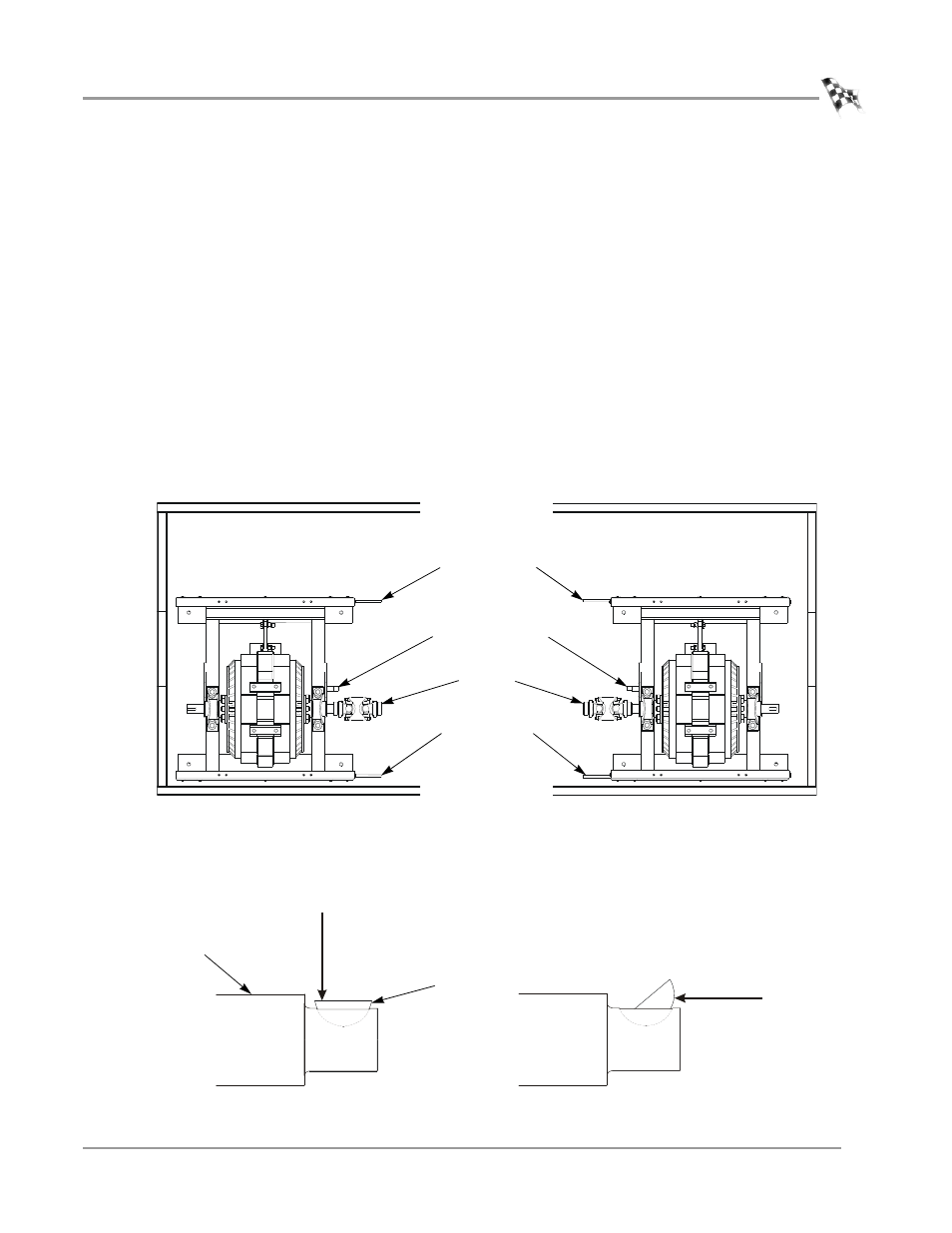
Figure 2-5: Left or Right Side Brake Set Up
Figure 2-6: Removing the Key
EB221
eddy current brake set up for left side
installation
eddy current brake set up for right side
installation
driveline
temperature sensor
connector plate
connector plate
apply force using
hammer and punch
apply force using
hammer and punch
shaft
key