Dynojet 250i: Pit Installation Guide User Manual
Page 44
In Ground Model 200iP/250iP Motorcycle Dynamometer Installation Guide
C H A P T E R 2
Blower and Monitor Support Installation
2-22
M
ARK
AND
D
RILL
B
LOWER
M
OUNTS
AND
S
UPPORT
A
RM
M
OUNTING
H
OLES
1
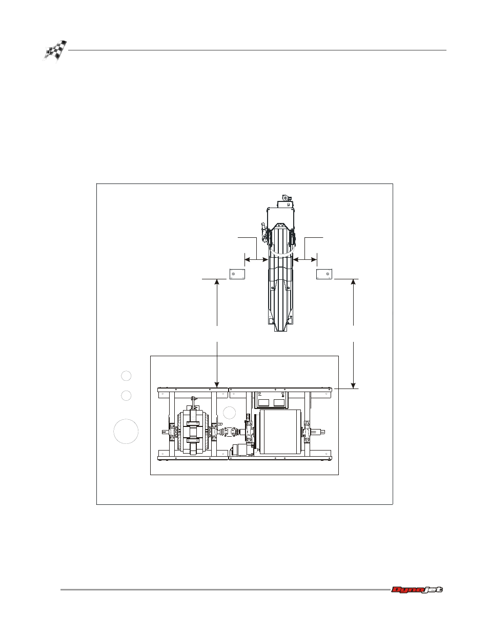
Using the carriage mounting plate and the dyno frame as reference, position the
support arm and optional blower mounts as shown.
Note: The high pressure blowers are an optional accessory. If you did not order
high pressure blowers, you will not need to install the blower mounts.
2
Using the mounting plates as a template, mark and drill the four 1/2-inch holes
needed to secure the blower mounts and support arm to the floor.
3
Install the Red Head anchors. Refer to Appendix A for installation instructions.
Figure 2-17: Blower Mounts and Support Arm Placement
PD158
111.76 cm
(44.00 in.)
111.76 cm
(44.00 in.)
24.13 cm
(9.50 in.)
24.13 cm
(9.50 in.)