Dynojet 250i: Pit Installation Guide User Manual
Page 71
I N S T A L L A T I O N
Pit Covers
Version 4
In Ground Model 200iP/250iP Motorcycle Dynamometer Installation Guide
2-49
1
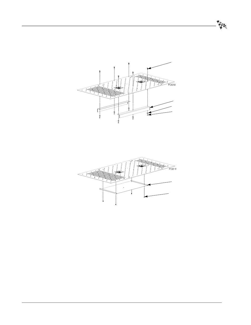
Remove the six 1/4-20-inch button-head screws, 1/4-inch flat washers, and
1/4-20-inch lock nuts securing the two angle supports to the bottom of the eddy
current brake cover and set aside.
Figure 2-42: Right Side Eddy Current Brake Cover—Angle Supports
2
Remove the four No. 6-32 pan head screws securing the heat shield and insulation
and set aside.
3
Move the heat shield and insulation to other side of the cover as shown in Figure
2-41 and secure with the four No. 6-32 pan head screws removed earlier.
Figure 2-43: Right Side Eddy Current Brake Cover—Heat Shield and Insulation
4
Move the two angle supports to the other side of the cover as shown in
Figure 2-41 and secure with the six 1/4-20-inch button-head screws, 1/4-inch flat
washers, and 1/4-20-inch lock nuts removed earlier.
5
Continue with the instructions for installing the pit covers.
screw
angle support
washer
nut
screw
heat shield