Dynojet 250i: Pit Installation Guide User Manual
Page 149
T H E T A C O N T R O L L E R
Power Adjustment
Version 4
In Ground Model 200iP/250iP Motorcycle Dynamometer Installation Guide
D-3
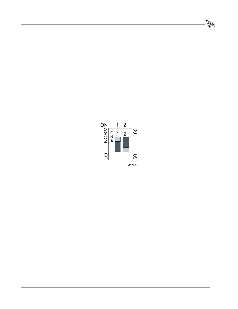
Power Line Voltage Adjustment—The theta controller is shipped with the dip
switch set for normal (NORM) line voltage. In the NORM position, the controller is
calibrated for a nominal 235 to 240 VAC line voltage.
In some cases in Europe or Japan, it may be necessary to set the dip switch to the LO
position when the AC line voltage is consistently around or below 225 VAC and
combined with reduced brake performance.
• Measure the AC line voltage with all normal AC loads running in the shop (lights,
heater, etc.).
• If the line voltage is reduced to or below 225 VAC and remains at these levels, move
the switch to the LO position. This will boost the output current with the lower AC
power voltages.
Note: If the AC power voltage returns above the 230 VAC range while the dip
switch is set to LO, overheating and damage to the eddy current brake or fuse
failure may result. Review the LO/NORM dip switch position setting and re-
measure your incoming AC line voltage.
Figure D-1: Theta Controller Dip Switch Settings