Routing the control panel and pendant cables – Dynojet 250i: Pit Installation Guide User Manual
Page 54
In Ground Model 200iP/250iP Motorcycle Dynamometer Installation Guide
C H A P T E R 2
Routing Cables
2-32
R
OUTING
THE
C
ONTROL
P
ANEL
AND
P
ENDANT
C
ABLES
1
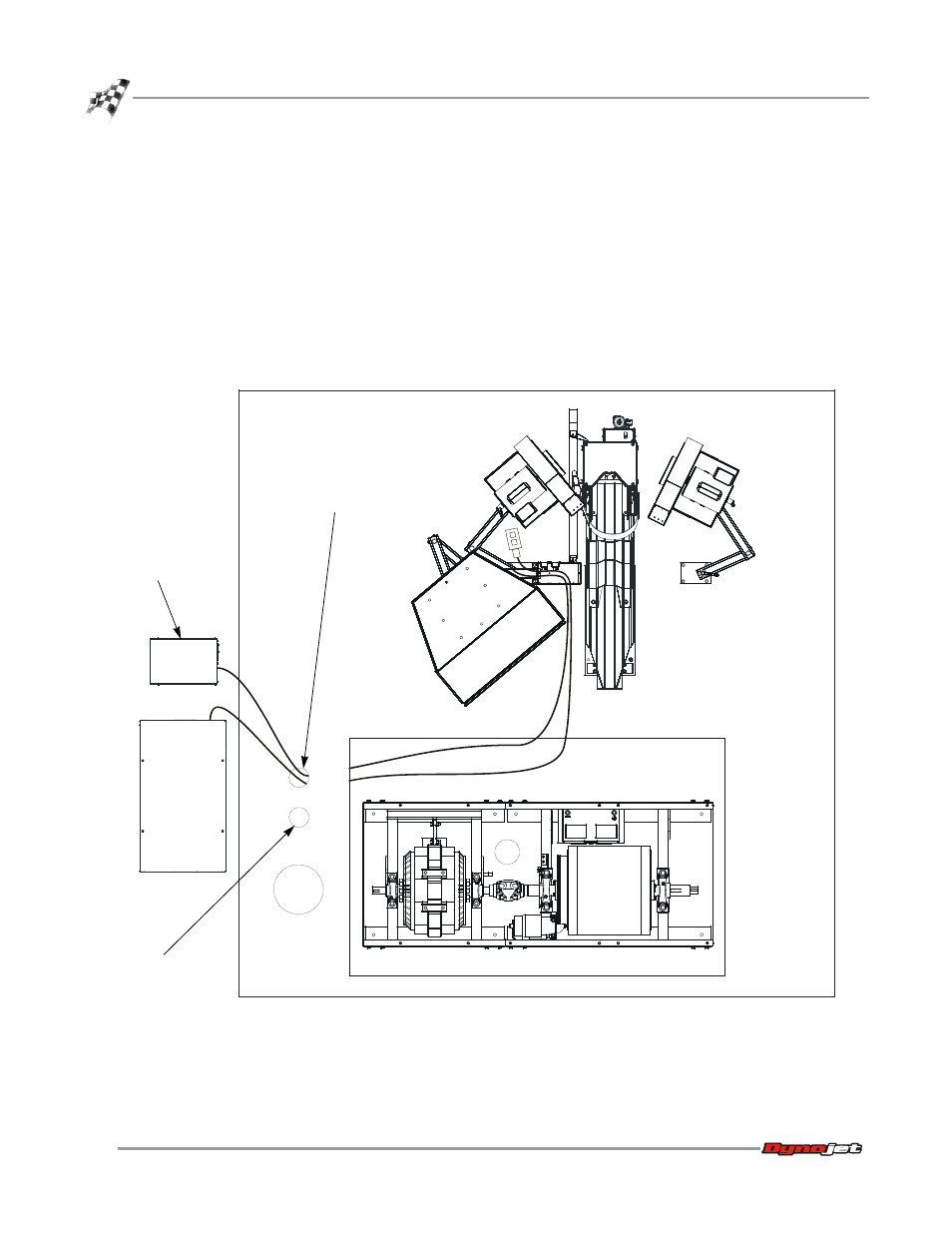
Route the control panel cable (P/N 76951502) from the CPI through the
designated communications pit conduit, through the pit, and out of the pit as
shown.
2
Route the pendant cable from the dyno electronics input/output module through
the same conduit and along the same path as the control panel cable. Refer to
“Dyno Electronics” on page 1-10.
Note: Be sure to keep the power and communications cables in different pit
conduits.
3
From the pit, route the cables through the junction box.
Figure 2-26: Route the Control Panel and Pendant Cables
PD185
CPI
dyno
electronics
route communications cables
in designated conduit
route power cables
in designated conduit