Rockwell Automation MinPak Plus DC Drives Kits User Manual
Page 9
8
ning procedures common to all Regenerative MinPak
Plus controllers. Most of the guidelines listed here must
be followed in order to achieve an efficient layout.
Guideline 1 Ċ The Regenerative MinPak Plus controller
is designed primarily as a wallĆ or panelĆmounted unit. It
is to be hung within 10
°
of vertical with the rear of the
Chassis firmly resting against the mounting surface. (Do
not position the Chassis on a horizontal surface.)
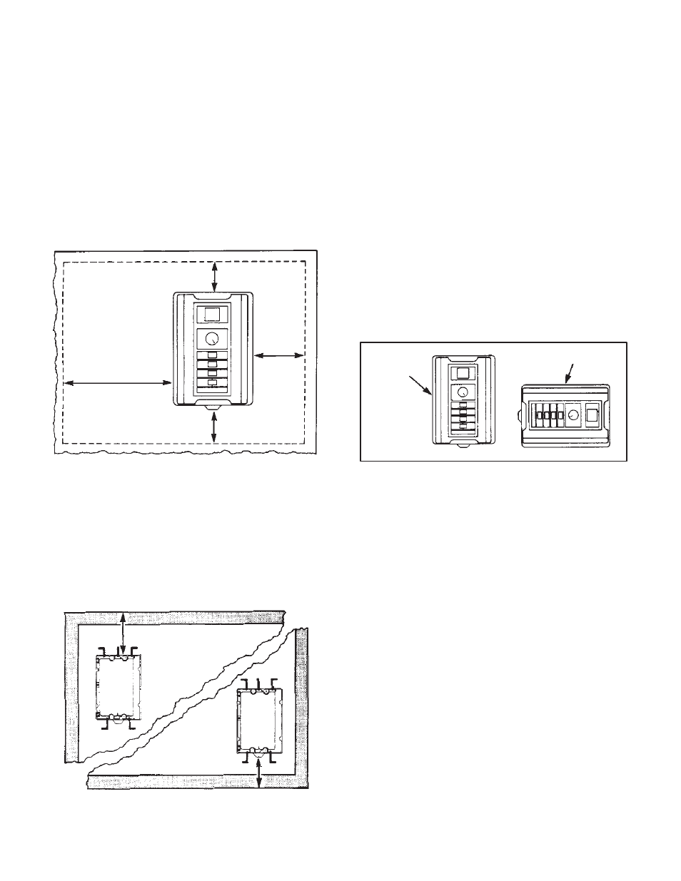
Guideline 2 Ċ It is necessary to leave at least a 2Ćinch
(50 mm) clearance around the three unhinged sides of
the Chassis. This unobstructed area allows for proper
air circulation through the fins of the heat sink. (Refer to
Figure 3.1.)
Guideline 3 Ċ Since the controller's Cover is hinged,
additional clearance must be provided on the fourth side
of the Chassis. (Refer to Figure 3.1.)
Do not
place
devices
in this
area.
11 in.
(275 mm)
2 in.
(50 mm)
2 in.
(50 mm)
2 in.
(50 mm)
Figure 3.1 - Open PanelMinimum Mounting Distances
Guideline 4 Ċ If mounting the controller within a larger
enclosure, do not place it directly in a corner. Leave at
least 8 inches (200 mm) from the top or 6 inches (150
mm) from the bottom of the enclosure. Also leave 8 inĆ
ches (200 mm) between the enclosure side wall and the
unhinged side of the controller. (Refer to Figure 3.2.)
Heat builds up at the cabinet's top and may exceed the
permissible inside ambient temperature upper limit. At
the cabinet's bottom, the unit must be high enough to alĆ
low air to flow upwards.
8 in.
(200 mm)
6 in.
(150 mm)
Figure 3.2 - Enclosure Mounting Minimum Distances
Guideline 5 Ċ Regardless of the above placement
guidelines, the user is responsible for providing ambient
temperatures that meet the controller's specifications.
For units mounted on an open panel or wall and using
the standard Cover, this range is 0
°
to 40
°
C (32
°
to
131
°
F). For units mounted in a ChassisĆonly configuraĆ
tion in a larger cabinet, this range is 0
°
to 55
°
C (32
°
to
131
°
F). Relative humidity must be kept between 5 and
95% without condensation if a Cover is not used.
Guideline 6 Ċ Keep in mind that the wells, which proĆ
vide incoming and outgoing wire channels, are designed
to accept threaded male conduit couplings. Plan controlĆ
ler placement on the wall or panel to allow for conduit
runs. Note also that two wells are 3/4"Ć14 pipe threads,
and three wells are 1/2"Ć14 pipe threads.
Guideline 7 Ċ Because of the diagonal design of the
heat sink, the Regenerative MinPak Plus controller ChasĆ
sis may be mounted in one of two orientations: first, with
the side containing three conduit wells at the top and, seĆ
cond, with the same side at the right. (The Cover, if used,
will swing to the left or, alternately, upward.) Refer to FigĆ
ure 3.3.
hinges
hinges
Figure 3.3 - Mounting Orientations
Guideline 8 Ċ If the controller is to be mounted in a largĆ
er enclosure and if the NEMA rating of that enclosure is
adequate, there is no absolute reason to use a Cover,
which is shipped as standard. (This assumes that a ReĆ
mote Operator Station is used.) However, the environĆ
ment of the application should be carefully considered
before making this decision.
Using the Regenerative MinPak Plus controller without a
Cover demands that the ambient environment around
the Chassis be relatively clean, free of flammable or
combustible vapors, chemical fumes, oil vapor, steam
and/or excessive dirt and moisture.
Guideline 9 Ċ If the controller is placed in a larger encloĆ
sure, do not place it so that the Cover, if used, cannot
swing open at least 90
°
minimum. Allowing for the full
110
°
swing aids subsequent installation and troubleĆ
shooting. (Note that the Cover may swing to the left or
upward, depending on the mounting orientation. Refer to
Figure 3.3.)
Guideline 10 Ċ Do not route the tachometer feedback
signal cable, if used, in the aĆc or dĆc conduits. Use a
dedicated steel conduit fixed in the proper well. Also use
the specified wire for this function.