Rockwell Automation MinPak Plus DC Drives Kits User Manual
Page 32
31
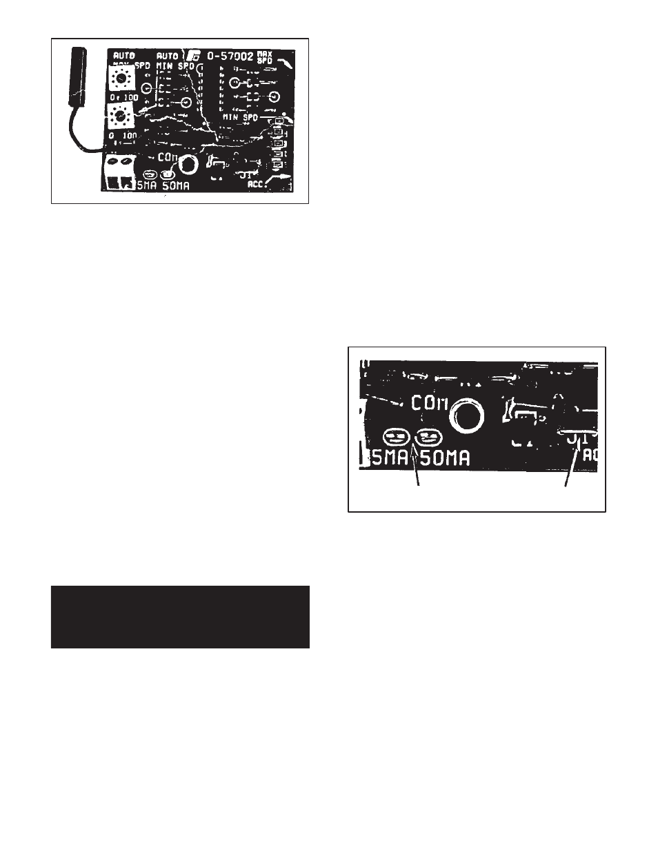
Figure 6.9 - Instrument Interface Kit
The Auto Minimum Speed potentiometer on the Module
can be set so that the drive runs at a preset minimum
speed (zero to 50%) with a minimum output signal from
the process instrument. The Auto Maximum Speed poĆ
tentiometer on the Module can be set so that the drive
runs at 50% to base speed with a maximum output signal
from the instrument. Other relationships within these paĆ
rameters are also possible, and they allow operation
over a larger speed range than the 5:1 range provided by
the process controller.
The Kit contains a Module that has a jumper that must be
connected by the user to select one of two maximum inĆ
put signals: 5 mA or 50 mA. There is also a mounting
screw. The Kit may be used alone to provide full, autoĆ
matic drive control, or it may be used with an optional
AUTO/MANUAL selector switch on the Operator Control
Station. This switch may be used to manually override
the external dĆc signal. (In the MANUAL position, the
drive follows the SPEED potentiometer on the Station.)
The user supplies the required lengths of specified signal
wire. (Refer to Table 6.C.) A process instrument controlĆ
ler, or other transducer with a dĆc milliampere output, is
also required.
NOTE: If the Operator Control Station contains an AUTO/
MANUAL selector switch, it is necessary to remove jumpĆ
er J1 from the Instrument Interface Module and J4 (Local
Station only) on the Regulator Module. (Refer to Figure 6
10.) Do this before placing the Module on the Regulator
Module.
DANGER
APPLICATION MUST NOT RELY ON ZERO
SPEED SETTING FOR SAFETY. SERIOUS OR
FATAL INJURY MAY RESULT.
To install the Kit, follow these procedures. The following
explanation assumes that the initial wiring was carried
out. Refer to Paragraph 3.7 which is a discussion of
tachometers, but may be generally applied here if differĆ
ences in wire entry and routing are kept in mind. For this
information refer to Figure 3 7.
Step 1 Ċ Orient the Module over the dedicated area
marked REFERENCE on the Regulator Module. just over
the 5 pins. (Refer to Figure 7.6.) Lower it so that the pins
pass through the guides on the Module. Use the screw
to secure it.
Step 2 Ċ Connect the external reference signal wires to
the terminal strip on the Module. Plus (+) on the left, miĆ
nus (-) on the right. Do not strip more than 1/8 inch (3
mm) of insulation off since shorts could occur at exposed
points. Maintain the twisted character as long as posĆ
sible.
Step 3 Ċ At this point refer to Paragraph 6.5.1 if the ReĆ
generative MinPak Plus is to follow a process instrument
controller signal. Refer to Paragraph 6.5.2 if the RegenĆ
erative MinPak Plus is to be set at a preset speed for conĆ
tinuous operation. The procedures differ.
6.5.1 Installing Instrument Interface Ċ When the Kit
is to be used as an instrument interface, follow these
Steps.
Step 1 Ċ Determine whether the maximum input signal
is between 0 to 5 mA or 5 to 50 mA. Locate the black pigĆ
tail jumper on the Module. (Refer to Figure 6.10.) CarefulĆ
ly place it on the directly corresponding pin, both of
which are clearly marked.
mA pins
Jumper J1
Figure 6.10 - Jumper J1, mA Pins
Step 2 Ċ This Step assumes that the complete drive sysĆ
tem, including the controller, has been successfully
started up and debugged according to Section 4 thru
Paragraph 4.4.1. It is now necessary to carry out a powerĆ
on test. Place the controller in the AUTO mode, if it is so
equipped. Set the process instrument controller for miniĆ
mum output. Locate the Auto Minimum Speed potenĆ
tiometer on the Interface Module Using a small insulated
screwdriver, adjust it for the desired minimum motor
speed. (CCW decreases speed.)
Step 3 Ċ Set the process instrument controller for maxiĆ
mum output. Locate the Auto Maximum Speed potenĆ
tiometer. Adjust it for the desired maximum motor speed.
(CW increases speed, CCW decreases it.)
Step 4 Ċ Since there is some interaction between these
two potentiometers, at times it may be necessary to work
back and forth to achieve precise adjustments.
6.5.2 Installing Preset Speed Ċ When the Kit is to be
used as a simple preset speed device follow these Steps.