Rockwell Automation MinPak Plus DC Drives Kits User Manual
Page 29
28
Step 4 Ċ Locate the area on the Regulator Module
where the two connectors will connect. (Refer to Figure
4.2 or 7.6.) Note there are two sets of pins. Mate the conĆ
nector with the red wire in the end position connecting
to the pin marked 32 (RED). Mate the second connector
with the green wire in the end position connecting to the
pin marked 28 (GRN).
Step 5 Ċ Attach the ground (green) wire to the Auxiliary
Bracket mounting screw located halfway down the
hinged edge. (Refer to Figure 3.6.)
NOTE: For a Local Operator Control Station, no other
connections are necessary.
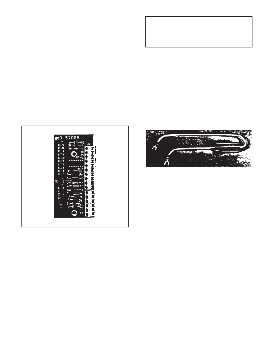
6.2 Remote Operator Station Ċ The optional Remote
Operator Adapter Kit allows the locating of operator
controls some distance from the Chassis.
In addition to a Remote Operator Adapter Module, this
Kit contains all the mounting hardware necessary to seĆ
cure the Module. (Refer to Figure 6.3.) However, one
may also need to order two additional options from ReĆ
liance Electric. (Refer to Paragraph 2.1.2.)
Figure 6.3 - Remote Adapter Kit
Step 1 Ċ Locate the area on the Regulator Module
where the Remote Operator Adapter Module is to be
mounted. Place the Module in the proper orientaĆ
tion: the edge with 10 holes should be aligned over
the 10 pins. (This area is marked RED 32 in Figure
7.6.) Carefully, slowly and gently press the Module
down on the pins until it bottoms out. Use the two
screws to secure it.
Step 2 Ċ Based on the specific control capability of the
Remote Operator Station chosen, select the required
wires specified in Table 6.C.
Step 3 Ċ Draw the wires into the Chassis through the
dedicated conduit. (Refer to Figure 3.7 ) Then cut indiĆ
vidual wires to lengths required for connection to the
kit's terminal strip. Wire according to Figure 3.8.
WARNING
WARNING EXCESSIVE LENGTHS OF BARE
WIRE COULD CAUSE SHORTS AND/OR
GROUNDS. STRIP MINIMAL INSULATION
FROM EACH WIRE.
Step 4 Ċ Visually inspect all wiring. Check wire placeĆ
ment against diagrams. Look for grounds and shorts
caused by broken insulation. Make sure the conduit is
grounded.
Step 5 Ċ Attach the blank Faceplate onto the Cover.
(Follow procedures outlined in Paragraph 6.1, Steps 1,
2, 3 but ignore the references to connectors.) Be sure to
attach the ground wire.
6.3 Dynamic Braking Ċ The standard Regenerative
MinPak Plus controller allows a drive motor to coast to
rest after the STOP switch is pressed. Optionally, a user
may install a Dynamic Braking Kit. (Refer to Figure 6.4.)
Its use allows a rapid, shockless stopping of the drive
motor.
Figure 6.4 - Dynamic Braking Kit
Dynamic Braking is not a mechanical holding brake. It
will not hold the shaft in place, nor will it prevent the motor
from turning once motion has stopped.
The Dynamic Braking option is actually a resistor conĆ
nected across the motor armature (Refer to Figure 7.3 in
which a schematic is shown.) It allows a motor to act as
a generator; the rotating mechanical (kinetic) energy is
converted into electrical energy that is dissipated in the
form of heat by the Dynamic Braking resistor. Note that
the resistor is sized for infrequent stops; thus, users must
allow time between stops for heat dissipation.
When ordering the Kit, it is necessary to specify Part
Numbers according to horsepower and voltage ratings.
(Refer to Table 8.A.)
The Dynamic Braking Kit contains the resistor and two
mounting screws. No other Reliance Electric options are
required, and no other userĆsupplied equipment is necĆ
essary.
To install the Kit, follow these procedures.
Step 1 Ċ It is easier to mount the Kit when the unit is in
a horizontal position, as is possible at initial installation.
Step 2 Ċ Remove the screws holding the Circuit Breaker
bracket. Move the assembly out of the way.
Step 3 Ċ Disconnect power leads A1 and A2 from 1TB;
disconnect leads 145 and 147 from the DV/DT Module;
disconnect the two current transformer feedback conĆ
nections (192, 193 and 292, 293, respectively) to the upĆ
per rightĆhand corner of the Regulator Module. Move the
assembly out of the way.