Rockwell Automation MinPak Plus DC Drives Kits User Manual
Page 34
33
41
42
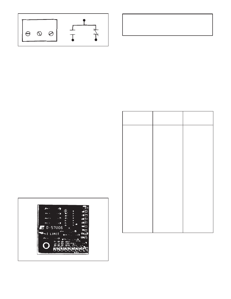
COM
43
COM
41
42
43
NC
NO
Figure 6.14 - External Wiring, Auxiliary M
Users supply the wiring to external devices. Size is deĆ
pendent on the specific application. It should not exceed
AWG No. 14.
The maximum rating of each contact is 1 ampere at 30
VDC (resistive) or 0.5 ampere at 120 VAC (resistive).
Under no circumstances should these contacts be used
to control brakes or other power loads.
To install the Kit, follow these procedures.
Step 1 Ċ Mount the Auxiliary M Contact Module on the
center of the Auxiliary Mounting Bracket. Note that
orientation is important. The overhanging edge of the asĆ
sembly must hang over the Regulator Module. Then
snap the assembly into the Bracket.
Step 2 Ċ Connect the threeĆwire harness to the RegulaĆ
tor Module. Locate the letters AUX M printed on the ModĆ
ule near a threeĆpin connector. (Refer to Figure 7.6.) The
connector fits on the bayonet pins. Note that the yellow
wire must connect with the pin marked YEL 38 on the
Regulator Module.
Step 3 Ċ Draw external wiring into the Chassis. Follow
Figure 3.7 for conduit access and routing.
Step 4 Ċ Route external wiring to the Module's terminal
block. Do not strip more than 1/4 inch (6 mm) of insulaĆ
tion from the wires since shorts could occur at exposed
points.
6.8 Test Meter Adapter Ċ Measuring and monitoring of
Regenerative MinPak Plus regulator voltages can be
safely and conveniently carried out with the optional Test
Meter Adapter Kit. (Refer to Figure 6.15.) It acts as an inĆ
terface between the Regulator Module and a user's voltĆ
meter.
Figure 6.15 - Test Meter
CAUTION: Under no circumstances should the
probes of a meter be connected directly to the pins
on the Regulator Module. Permanent damage to
the solid state components can occur.
The Kit contains a Module and a mounting screw. Except
for the voltmeter, no other equipment is necessary. The
meter should be a multimeter having a sensitivity of
20,000 ohms per volt minimum. (Simpson Model 260,
Triplett Model 630, or equivalents are acceptable.)
To install and use the Kit, follow these procedures.
Step 1 Ċ Orient the Adapter Module over the area on the
Regulator Module marked TEST, just over the 9 pins. (ReĆ
fer to Figure 7.6.) Lower it so that the pins pass through
the guides on the Module. Use the screw to secure it.
Step 2 Ċ For use, refer to Table 6.D where the function
is shown in relation to the test terminals to be used. The
normal operating voltages are also shown.
Table 6.D - TEST ADAPTER TERMINALS, READINGS
FOR FUNCTION
USE
TERMINALS:
NORMAL
INDICATION
(VDC):
Unregulated
+20 VDC
Power Supply
Unregulated
*20 VDC
Power Supply
Regulated
+11.2 VDC
Power Supply
Regulated
*11.2 VDC
Power Supply
LVTU (linear
voltage time unit)
Input
Major Loop
Feedback
Forward/Reverse
Driver Outputs
+456
*357
*471
+357
+356
*357
*371
+357
+826
*357
*819
+357
*816, *817
+356
16-28
16-28
10.8-11.5
10.8-11.5
0-8.0
0-4.0
On 10 VDC scale,
increase of
approx. 1 VDC
occurs when
drive is started.
6.9 Master Isolated Reference Receiver Ċ The addiĆ
tion of the optional Master Isolated Reference Receiver
Kit allows the Regenerative MinPak Plus to receive and
decode a PWM speed reference signal from the Master
Isolated Reference Transmitter. The Receiver Kit consists
of two printed circuit boards: a Switch Receiver Module
and a Reference Receiver Module which are mounted on
the Regenerative MinPak Plus Regulator Module. (Refer
to Figure 6.16.)