Rockwell Automation MinPak Plus DC Drives Kits User Manual
Page 36
35
Step 5 Ċ Using a twisted pair, connect the external refĆ
erence wires (wires 1 and 2) from the external Master
Isolated Reference Transmitter to the terminal block on
the Reference Receiver Module in the controller cabiĆ
net. Connect wire 1 to terminal 1 and wire 2 to termiĆ
nal 2.
NOTE: Do not strip more than 1/8 inch (3 mm) of insulaĆ
tion off the ends of the wires because a short circuit
could occur at any point where the bare wire is exposed.
Maintain the twisted configuration of the two wires as
much as possible.
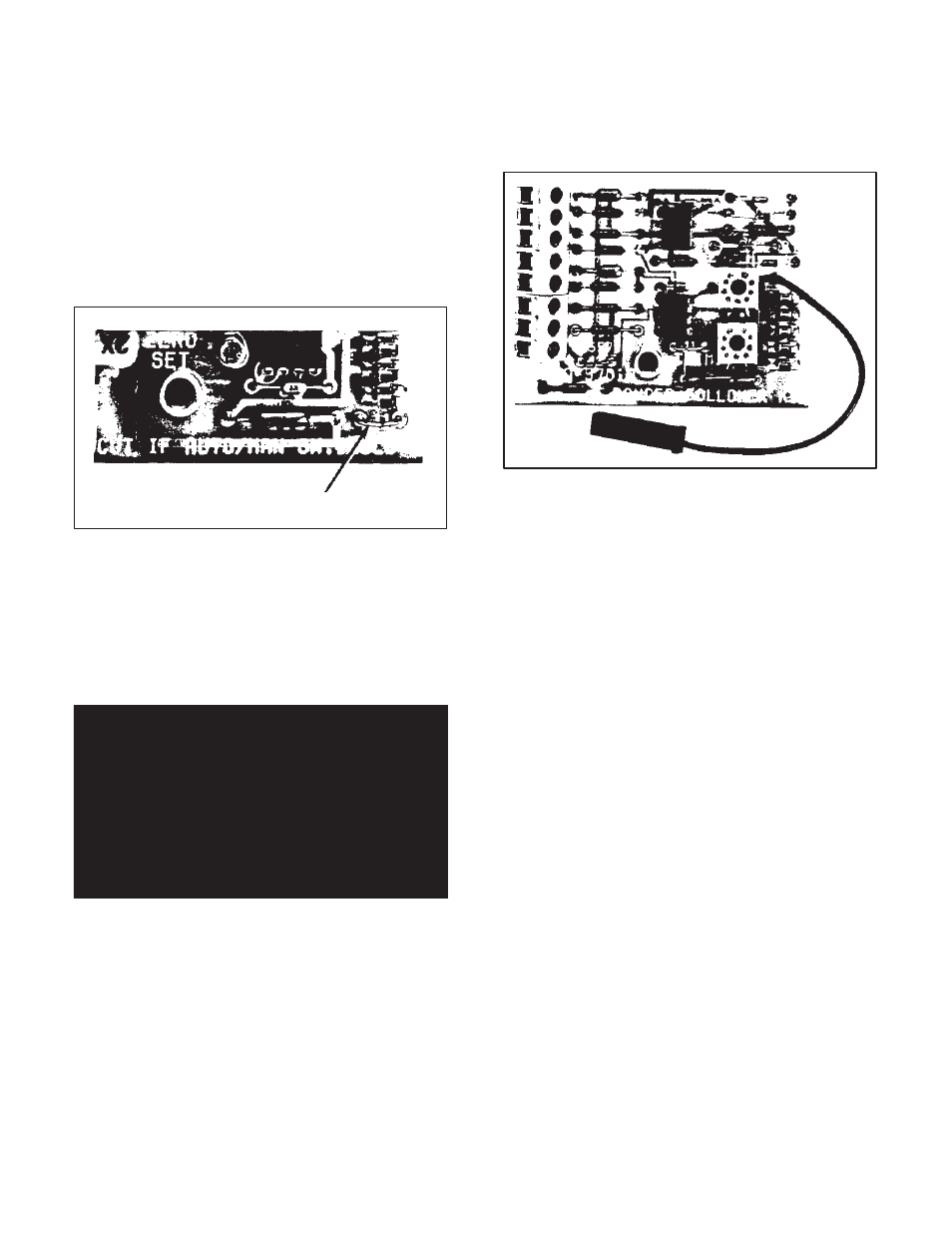
Step 6 Ċ If an AUTO/MANUAL selector switch is inĆ
cluded in the Operator Control Station, cut jumper J1 on
the Reference Receiver Module. (Refer to Figure 6.18.)
Jumper J1
Figure 6.18 - Jumper J1 on Reference
Receiver Module
Step 7 Ċ With the MASTER Speed potentiometer on the
Master Isolated Reference Transmitter set at zero, deĆ
press the START pushbutton on the Master Isolated RefĆ
erence Transmitter. Adjust the ZEROSET potentiometer
on the Reference Receiver Module to obtain zero speed
of the drive motor.
DANGER
ALTHOUGH ZERO SET ADJUSTMENT ON THIS
KIT ALLOWS FOR ADJUSTMENT DOWN TO
ZERO SPEED, THIS ZERO SPEED SETTING
MUST NOT BE USED WHERE THE OPERATOR
MAY RELY ON A MAINTAINED ZERO SPEED.
ELECTRICAL NOISE, IMPROPER WIRING,
POWER LINE, OR MALFUNCTIONING COMĆ
PONENTS MAY CAUSE THE DRIVE TO TURN
ON WHILE AT THE ZERO SPEED SETTING.
6.10 Dancer Follower Ċ The Dancer Follower Kit allows
the Regenerative MinPak Plus to be controlled automatiĆ
cally in response to a speed reference generated by a
line speed signal and trimmed by a Dancer potentiomeĆ
ter. Applications include web process lines where a drive
must closely follow or maintain the position of a dancer.
The Kit contains the Dancer Follower Module and a
mounting screw. Although the Regenerative MinPak Plus
can use the Kit for exclusive automatic speed control, if
manual override control is needed, an AUTO/MANUAL
selector switch must be used on the Local or Remote OpĆ
erator Control Station. (Refer to Table 2.B.) In the MANUĆ
AL position, the drive responds to the SPEED potentiomĆ
eter setting. In AUTO, it follows only the external signals
and does not respond to manually input speed change
commands. (Refer to Figure 6.19.)
Figure 6.19 - Dancer Follower Module
The Kit is designed to accept a line speed input signal of
4 to 10 VDC to obtain maximum speed. The input impedĆ
ance between the line speed input terminals 57 and 726
is approximately 25,000 ohms. The Dancer potentiomeĆ
ter will provide up to a 20% trim to the line speed signal.
The user must supply the required lengths of the speciĆ
fied signal wire. (Refer to Table 6.C.) A Dancer potentiomĆ
eter and an optional Dancer Position potentiometer are
also to be supplied by the user.
To install the Kit, follow these procedures.
Step 1 Ċ Refer to Figure 7.6 and note the heavy border
area in the center of the Regulator Module marked REFĆ
ERENCE. This is the area where the Dancer Follower
Module is to be mounted. Place the Dancer Follower
Module in the proper orientation so the pin guides on the
Module are aligned over the set of five pins on the ReguĆ
lator Module. Lower the Dancer Follower Module so the
pins pass through the pin guides and the mounting
spacer seats in the mounting hole. (It may be necessary
to remove a protective plastic cap from the pins.) Secure
the Module with the supplied screw.
Step 2 Ċ Connect the black pigĆtail jumper of the Dancer
Follower Module to pin 319 on the Regulator Module.
(Pin 319 is the top pin of a group of two pins along the
right hand edge.)
Step 3 Ċ Using a twisted pair, connect the external line
speed input to the terminal strip of the Dancer Follower
Module. The plus (+) wire is connected to terminal 726
and the minus (-) wire is connected to terminal 57.
NOTE: Do not strip more than 1/8 inch (3 mm) of insulaĆ
tion off the ends of the wires because a short circuit could
occur at any point where the bare wire is exposed. MainĆ
tain the twisted configuration of the two wires as much as
possible.