Rockwell Automation MinPak Plus DC Drives Kits User Manual
Page 15
14
Take these two figures and relate them to Table 3.B. Read
across to the right column, where the 100% voltage figĆ
ure is indicated. Place the jumper on the Module's pin
that corresponds to this figure.
Table 3.B - TACHOMETERVOLTAGE SCALING
MOTORBASE
SPEED
(rpm)
TACHOMETER
(volts/1000 rpm)
100%
VOLTAGE
CONNECTION
1150
1750
1150
3450
1750
1150
3450
1750
ă20 VDC
ă20 VDC
ă50 VDC
ă20 VDC
ă50 VDC
100 VDC
ă50 VDC
100 VDC
23
35
58
69
88
115
175
175
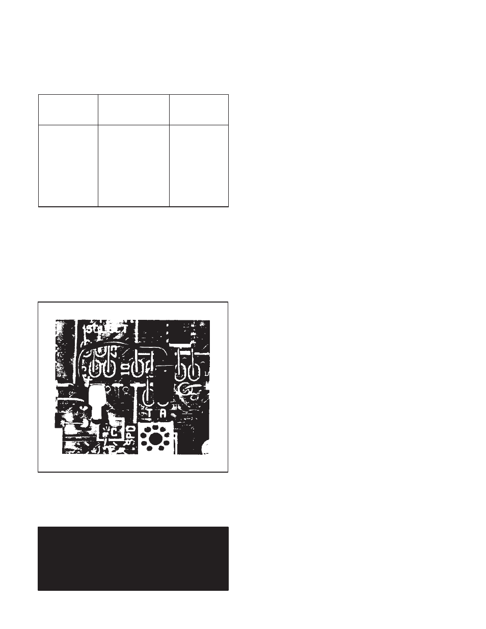
Step 3 Ċ The Feedback Jumper on the Regulator ModĆ
ule must be connected for tachometer feedback. (Refer
to Figure 3.9.) Place the Regulator Module's fixed black
jumper on the pin marked T.
Figure 3.9 - Feedback Connection on Regulator
Module
DANGER
IMPROPER TACHOMETER CONNECTION WITH
RESPECT TO POLARITY WILL RESULT IN UNĆ
CONTROLLED MOTOR SHAFT ACCELERATION
WHICH MAY RESULT IN SEVERE PERSONAL INĆ
JURY AND/OR EQUIPMENT DAMAGE.
NOTE: A recommended way to check the polarity of the
tachometer is to run the controller as a Voltage RegulaĆ
tor while observing the tachometer output with a dĆc voltĆ
meter.
Step 4 Ċ This Step assumes that the complete drive sysĆ
tem, including the controller, has been successfully
started up and debugged according to Section 4 thru
Paragraph 4.4.1. It is necessary to carry out a powerĆon
test. Set the SPEED potentiometer at approximately 25%
of full rotation. Start the drive. It should run as set. If it acĆ
celerates to full speed, the tachometer is not providing a
signal or is improperly connected.
Stop the drive, turn off all power, and check and correct
the leads to the Tachometer Module's terminal strip. ReĆ
peat the test with power on in order to confirm that proper
feedback signals are being received by the regulator.
If erratic behavior continues, check the placement of the
two pigĆtail jumpers against Steps 2 and 3.
Step 5 Ċ The Maximum and Minimum Speed PotenĆ
tiometers should now be adjusted to Paragraphs 4.4.2
and 4.4.3. Be sure to follow 4.4.4, and 4.4.5.
After wiring, examine connections at both ends to make
sure wire connections were correctly made. Confirm wire
identification. Examine the firmness of connections.
3.8 Operator Station Wiring Ċ Both the local Operator
Control Faceplate and the Remote Operator Control StaĆ
tion are purchased as options. Thus, they are discussed
in Section 6. Modification Kits.
3.8.1 Local Faceplate Ċ If the Regenerative MinPak
Plus controller is to be used for local'' operator control,
it is necessary to mount one of five optional Faceplates
in the cutout on the Chassis Cover. (''Local" is defined as
having all control switches and potentiometers on the
controller's Cover.)
A local configuration requires no external wiring through
conduits. Complete procedures are listed at Paragraph
6.1.
3.8.2 Remote Station Ċ If the Regenerative MinPak
Plus controller is to be used for remote" operator conĆ
trol, it is necessary to mount an optional blank Faceplate
in the cutout on the Chassis Cover. Also, an optional ReĆ
liance Electric Remote Operator Control Station must be
wired to the Remote Operator Station Kit mounted in the
controller. ("Remote" is defined as not having any control
switches mounted on the Chassis Faceplate.)
A remote configuration requires userĆsupplied external
wiring between the Station and the controller. These
wires must run through a dedicated conduit and enter
the controller through an assigned conduit well. (Refer to
Figure 3.7.)
3.9 50ĆHz Operation Ċ There may be cases when the
Regenerative MinPak Plus controller is to be operated
continuously on 50 Hz. If so, two resistors should be reĆ
moved from the Regulator Module for optimum perforĆ
mance. (Refer to Figure 3.10.)
3.10 Isolation Transformers Ċ Although an autoĆtransĆ
former may be required because of aĆc line voltage levĆ
els, it is unable to provide a number of benefits standard
with an isolation transformer. (Refer to Guideline 16.)
Note also Guideline 15 concerning the position of the aĆc
line disconnect switch in relation to the transformer.