Rockwell Automation MinPak Plus DC Drives Kits User Manual
Page 31
30
Step 6 Ċ Replace the Circuit Breaker bracket and reconĆ
nect the leads disconnected in Step 3.
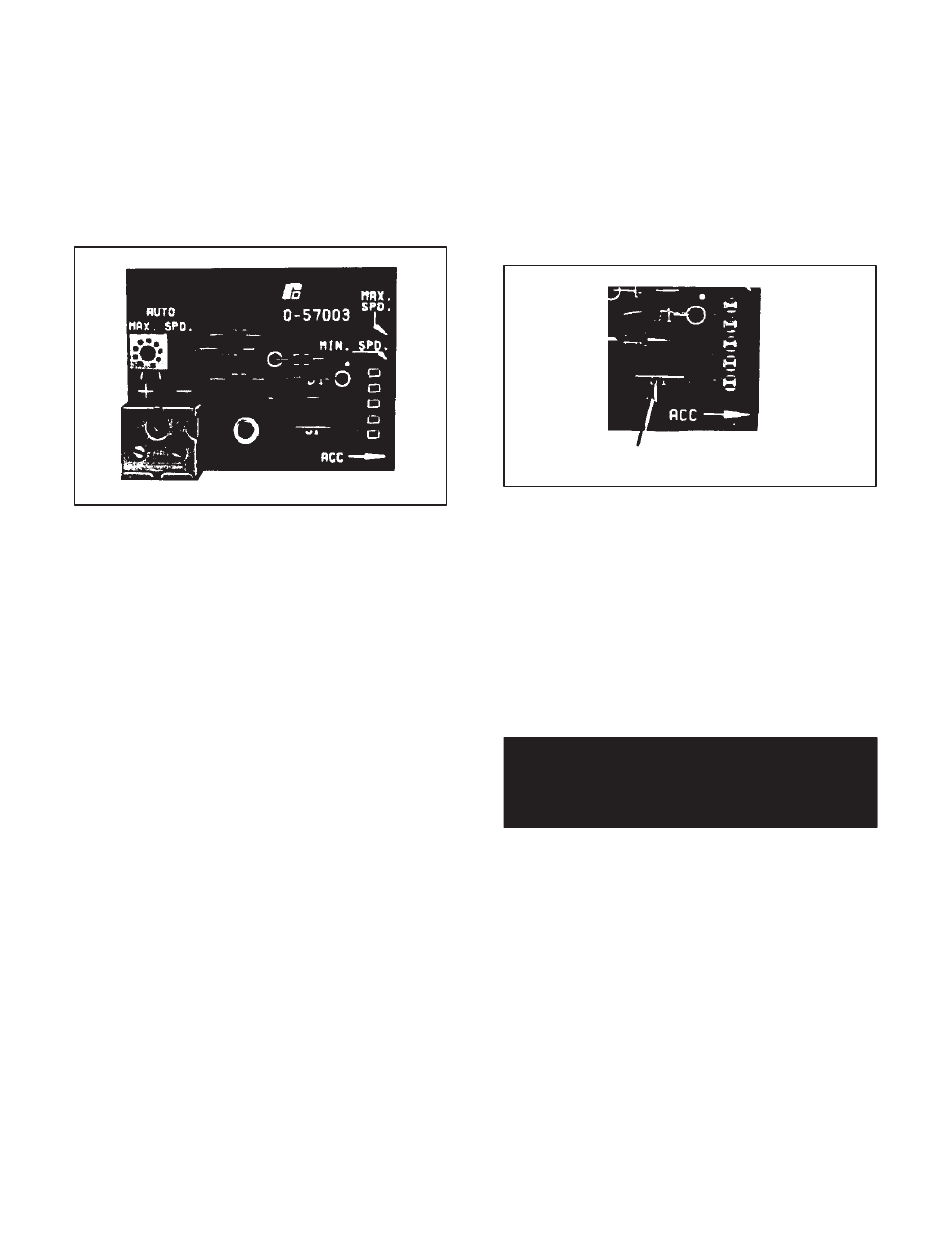
6.4 Voltage/Tachometer Follower Ċ The Voltage/
Tachometer Follower Kit allows the Regenerative MinPak
Plus to be controlled automatically in response to a
speed reference generated by a tachometer connected
to an entirely separate machine unit. Ideal applications
include automatic control systems where a second"
slave drive must closely follow the speed of a master
drive, or machine. (Refer to Figure 6.7).
Figure 6.7 - Voltage/Tachometer Follower
The kit is designed to accept an input signal of 25 to 250
VDC to obtain maximum speed. (The maximum permisĆ
sible input voltage is 250 VDC.) The input impedance beĆ
tween terminals is approximately 80,000 ohms. ThereĆ
fore, 100 VDC draw approximately 1.25 mA current from
the voltage source.
The Kit contains the Module and a mounting screw. AlĆ
though the Regenerative MinPak Plus can use the Kit for
exclusive automatic speed control, if manual override
control is needed, an AUTO/MANUAL selector switch
must be used on the Operator Control Station, Local or
Remote. (Refer to Table 2.B.) In the MANUAL position,
the drive response to the SPEED potentiometer setting.
In AUTO, it follows only the external signal and does not
respond to manually input speed change commands.
The user must also supply required lengths of the speciĆ
fied signal wire. (Refer to Table 6.C.) No other equipment
is necessary although some changes may be necessary
on the Module.
Step 1 Ċ In general, follow the wiring procedures outĆ
lined at Paragraphs 3.7 and 4.2.4, but keep in mind that
there are location and wire routing differences. Draw the
twistedĆpair signal wires into the Chassis through the
designated conduit entry. (Refer to Figure 3.7.) Run the
wires up as shown.
Step 2 Ċ Orient the Voltage/Tachometer Follower ModĆ
ule over the REFERENCE area on the Regulator Module,
just over the 5 pins. (Refer to Figure 7.6.) Lower it so that
the pins pass through the guides on the Module. (It may
be necessary to remove a protective plastic cap from the
pins.) Secure the Module with the screw.
Step 3 Ċ Connect the wires from the tachometer to the
terminal strip on the Module. Plus (+) is on the left, minus
(-) on the right. Do not strip more than 1/8 inch (3mm)
of insulation off since shorts occur at exposed points.
Maintain the twisted character as long as possible.
Step 4 Ċ If an AUTO/MANUAL selector switch is used,
it is necessary to remove jumper J1 on the Module. (ReĆ
fer to Figure 6.8.) If, however, the controller is designed
to run automatically without manual speed control, J1
remains in place. In addition, remove jumper J4 on the
Regulator Module if an AUTO/MANUAL selector switch
is used.
Jumper J1
Figure 6.8 - Jumper J1
Step 5 Ċ This Step assumes that the complete drive sysĆ
tem, including the controller, has been successfully
started up and debugged according to Section 4 thru
Paragraph 4.4.1. It is not necessary to carry out a powerĆ
on test. Start the drive and place it in the AUTO mode, if
so equipped.
With a small, insulated screwdriver, adjust the AUto
Speed Calibration potentiometer on the Tachometer/
Follower Module until the drive reaches the desired
speed in relation to the reference input signal being reĆ
ceived.
DANGER
APPLICATION MUST NOT RELY ON ZERO
SPEED/INPUT SETTING FOR SAFETY. SERIOUS
OR FATAL INJURY MAY RESULT.
6.5 Instrument Interface/Preset Speed Ċ The RegenĆ
erative MinPak Plus can automatically follow a milliamĆ
pere signal from a process control instrument if the opĆ
tional Instrument Interface/Preset Speed Kit is installed.
(Refer to Figure 6.9.) Alternately, the Kit also permits the
drive to run continuously at a preselected speed.
The Instrument Interface Module accepts a 0 to 5, 1 to 5,
4 to 20 or 10 to 50 mA signal, which may be grounded
or ungrounded. The maximum input is 50 mA.
Typical applications include cases where the drive moĆ
tor's speed must be controlled and varied as a function
of such process variables as temperature, weight, fluid
flow and pressure.