Rockwell Automation MinPak Plus DC Drives Kits User Manual
Page 35
34
The Operator Control Station AUTO/MANUAL selector
switch is used to obtain local control or master reference
control of the individual drive. When the selector switch
is placed in the AUTO mode, the individual drive SPEED
potentiometer automatically is converted into a draw pot
adjustment for precise trim control between drives. The
only adjustment requirement is a zero set adjustment on
the Reference Receiver Module. Should the speed referĆ
ence wires become disconnected, the Regenerative
MinPak Plus will go to zero speed.
Master Isolated Reference controlled Regenerative MinĆ
Pak Plus's are ideally suited for multiple conveyor drives,
proportional pumps, feeder drives, web lines or other
similar operations which require multiple drives to follow
a common reference signal and provide hold back
torque.
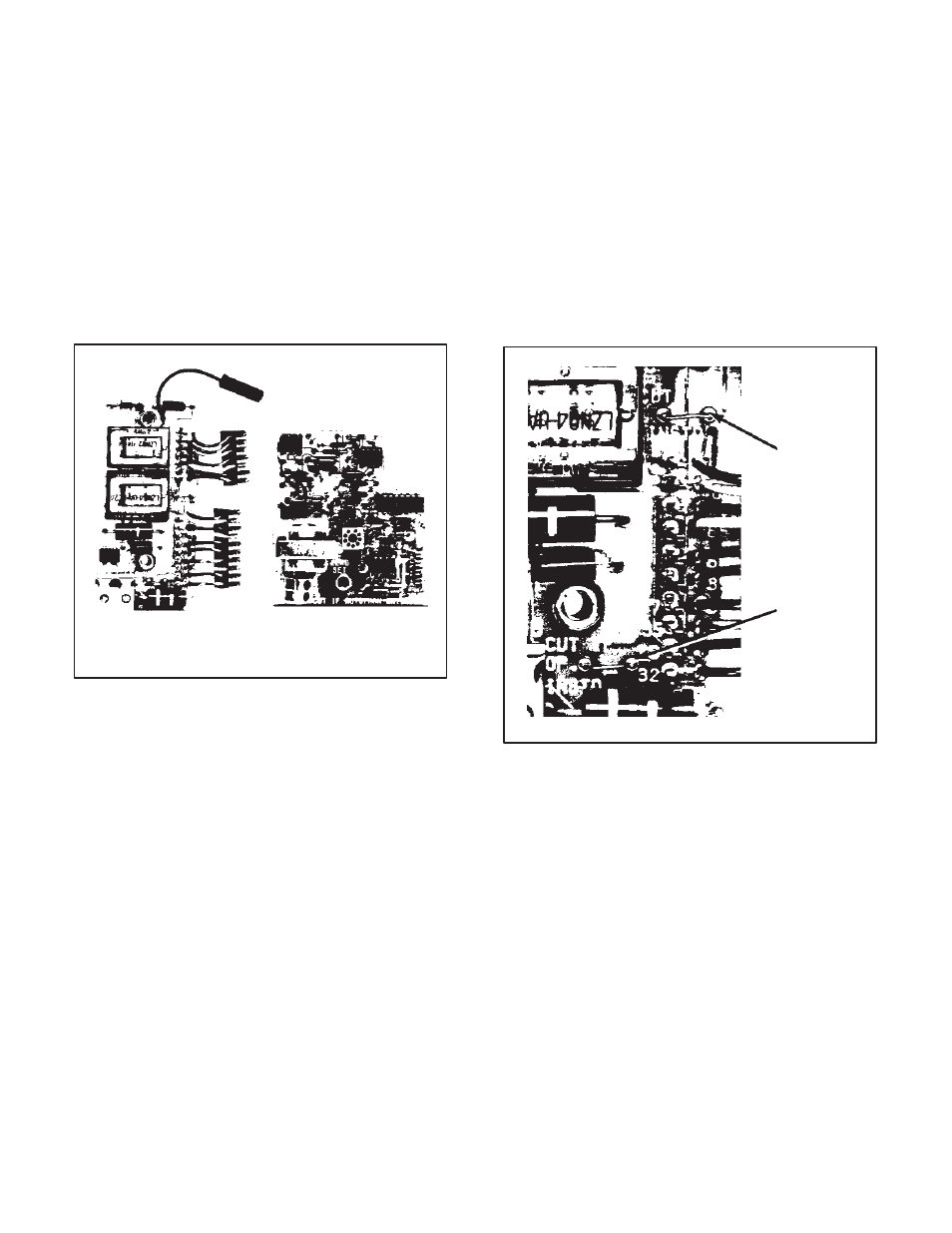
Switch Receiver
Module
Reference Receiver
Module
Figure 6.16 - Master Isolated Reference
Receiver Kit
To install the Kit, follow these procedures:
Step 1 Ċ Refer to Figure 7.6 and note the heavy border
area at the extreme leftĆhand side of the Regulator ModĆ
ule. This is the area where the Switch Receiver Module
is to be mounted. Place the Switch Receiver Module in
the proper orientation so the two connectors are aligned
over the two sets of pins (marked GRN 28 and RED 32).
Carefully, slowly and gently press the connectors down
on the pins until they bottom. Then, connect the black
pigĆtail jumper of the Switch Receiver Module to pin 40
on the Regulator Module.
Step 2 Ċ Fold the PC board over the top of the two conĆ
nectors so the mounting spacers fit into the mounting
holes.
If a Local Operator Station is being used, secure the
Switch Receiver Module with the two short screws proĆ
vided. The Local Operator Station is then mounted and
connected to the two sets of pins on the Switch Receiver
Module as described in paragraph 6.1.
If a Remote Operator Station is being used, mount the
Remote Operator Adapter Module on top of the Switch
Receiver Module and secure the two PC boards with the
two long screws provided with the kit as described in
Paragraph 6.2. See Figure 7.4 for proper connections to
the Switch Receiver Module and Remote Operator
Adapter Module. Refer to notes 35 and 36 in Figure 7.4.
NOTE: The external startĆstop wires from the Master IsoĆ
lated Reference Transmitter (wires 189 and 288) must be
connected to the Switch Receiver Module (Refer to Step
4.) before mounting the Remote Operator Adapter ModĆ
ule on the Switch Receiver Module. Jumpers J1 and J2
on the Switch Receiver Module (Refer to Figure 6.17.)
must be cut when Local or Remote Operator Stations are
used. These jumpers are left connected when only conĆ
trol from the Master Isolated Reference Transmitter is deĆ
sired.
Jumper J2
Jumper J1
Figure 6.17 - Jumpers J1 and J2 on Switch
Receiver Module
Step 3 Ċ Refer to Figure 7.6 and note the heavy border
area in the center of the Regulator Module marked REFĆ
ERENCE. This is the area where the Reference Receiver
Module is to be mounted. Place the Reference Receiver
Module in the proper orientation so the pin guides on the
Module are aligned over the set of five pins on the ReguĆ
lator Module. Lower the Reference Receiver Module so
the pins pass through the pin guides and the mounting
spacer seats in the mounting hole. (It may be necessary
to remove a protective plastic cap from the pins.) Secure
the Module with the supplied screw.
Step 4 Ċ Connect the external startĆstop wires (wires
189 and 288) from the external Master Isolated ReferĆ
ence Transmitter to the terminal block on the Switch ReĆ
ceiver Module in the controller cabinet.
NOTE: If remote operator devices are used, this step
must be completed before installing the Remote OperaĆ
tor Adapter Module (Step 1).