Rockwell Automation MinPak Plus DC Drives Kits User Manual
Page 20
19
Step 1 Ċ Attach one lead from the ohmmeter to the moĆ
tor frame to make a simple resistance check.
Step 2 Ċ Touch the test probe to each of the two power,
two thermostat, and two field leads to the motor. If the
reading to ground on any terminal is less than 100,000
ohms, a ground condition exists.
Step 3 Ċ If a ground condition exists, inspect the motor
thoroughly for internal shorts.
Step 4 Ċ When the grounding condition is corrected, reĆ
connect the conductors from the Regenerative MinPak
Plus controller.
4.3 Power On Adjustments Ċ Once all the preliminary
powerĆoff static adjustments have been performed with
acceptable results, the aĆc line power is to be applied to
the controller, but the load is not connected. It is imporĆ
tant to follow these steps closely. Observe all cautions
and warnings.
Note that these procedures progress on a cautious apĆ
proach. Under no circumstances should the sequence
be jumped to save time. Make sure each segment
checks out before moving on to another.
4.3.1 Preliminary Steps Ċ Assuming that all steps were
followed to this point, the following steps indicate how
the power may be applied to the controller.
Step 1 Ċ Close the Cover of the controller.
Step 2 Ċ On the Chassis Faceplate place the POWER
ON/OFF circuit breaker in the OFF position.
Step 3 Ċ On the Operator Station turn the SPEED and
TORQUE potentiometer, if used, to the zero position.
Step 4 Ċ Close the main aĆc disconnect. (Replace fuses
before closing the circuit, if necessary.)
Step 5 Ċ If no improper condition is observed, proceed
to the following Paragraphs.
DANGER
IF CIRCUIT BREAKER HAS TRIPPED, USER
MUST REMOVE THE COVER FROM THE DRIVE
AND DETERMINE IF A FIELD SUPPLY KIT IS
PRESENT. (SEE FIGURE 4.5.) IF FIELD SUPPLY
KIT IS PRESENT, THE FIELD SUPPLY KIT AND
ITS WIRING MUST BE INSPECTED FOR DAMĆ
AGE. AFTERCLOSING THE COVERAND REĆ
APPLYING POWERTO THE DRIVE, THE FIELD
VOLTAGE MUST BE REĆCHECKED FOR PROPĆ
ERVOLTAGE AT MOTORTERMINALS F1, F2. IF
THIS VOLTAGE IS BELOW 90% OF THE FIELD
VOLTAGE SPECIFIED ON THE MOTORNAMEĆ
PLATE, THE DRIVE MUST NOT BE STARTED
UNTIL PROPER VOLTAGE IS OBTAINED. FAILĆ
URE TO FOLLOW THIS PROCEDURE COULD
RESULT IN OVERSPEEDING THE MOTOR AND/
ORTHE MACHINERY COUPLED TO THE MOĆ
TORSHAFT AND POSSIBLE FATAL INJURY.
SEE PAGE 39 FOR TROUBLESHOOTING PROĆ
CEDURES.
4.3.2 Field Supply Check Ċ If the individual RegeneraĆ
tive MinPak Plus has an optional Field Supply Kit
installed, it must be checked while power is applied to
the unit. Since not all controllers have a Field Supply. it
must be determined if there is one before deciding
whether or not the check must be made. The following
controllers have a Field Supply:
D All controllers designed for 2 thru 5 hp drives.
D All controllers which are optionally fitted with a Field
Supply Kit. (These kits may be used only if the dĆc
motor has a wound field.)
(Refer to Paragraph 6.6 for more information.) Whether
or not the controller has a Field Supply may be quickly
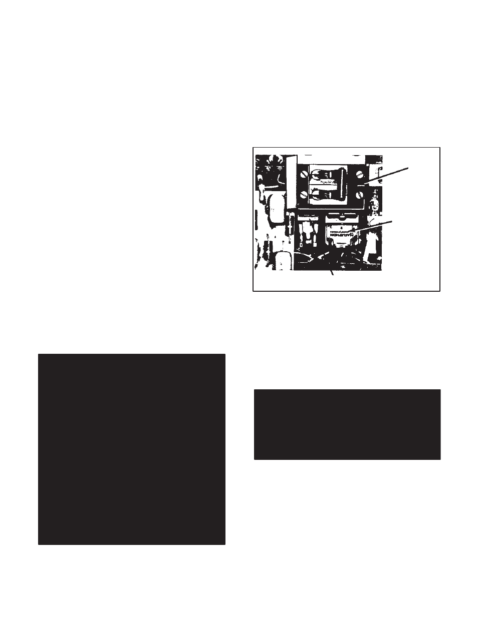
determined. (Refer to Figure 4.5.)
Terminal
Block
Diode Bridge
Bracket
Figure 4.5 - Field Supply in Controller
Step 1 Ċ Carefully open the Cover of the controller. (ReĆ
member to lift it directly up 2 inches (50 mm) before hingĆ
ing it around.)
Step 2 Ċ On the Cover, place the POWER ON/OFF cirĆ
cuit breaker in the ON position. (The following steps asĆ
sume that the main aĆc line disconnect is closed.)
DANGER
WITH AĆC POWERAPPLIED AND WITH THE
POWERON/OFF SWITCH IN THE ON POSIĆ
TION, HAZARDOUS VOLTAGE EXISTS IN THE
CONTROLLER. EXERCISE EXTREME CAUTION
WHEN PERFORMING THESE TESTS. PERĆ
SONAL INJURY CAN RESULT.
Step 3 Ċ Use a voltmeter to measure the dĆc voltage
across F1 and F2. (Either slot of the terminal barrier is acĆ
ceptable. This is called out as 3TB on diagrams.) For a
controller with a 115 VAC input, the voltage across F1
and F2 should be approximately 100 VDC For a 230 VAC
input, the voltage should be approximately 200 VDC.
Step 4 Ċ If the proper voltage cannot be read, place the
POWER ON/OFF circuit breaker in the OFF position. DisĆ
connect the aĆc line power. (Do not remove or apply powĆ
er solely with the main disconnect.) Check the Field SupĆ
ply Kit for proper installation. (Refer to Paragraph 6.6 and
to Section 7 Troubleshooting.)