Rockwell Automation MinPak Plus DC Drives Kits User Manual
Page 30
29
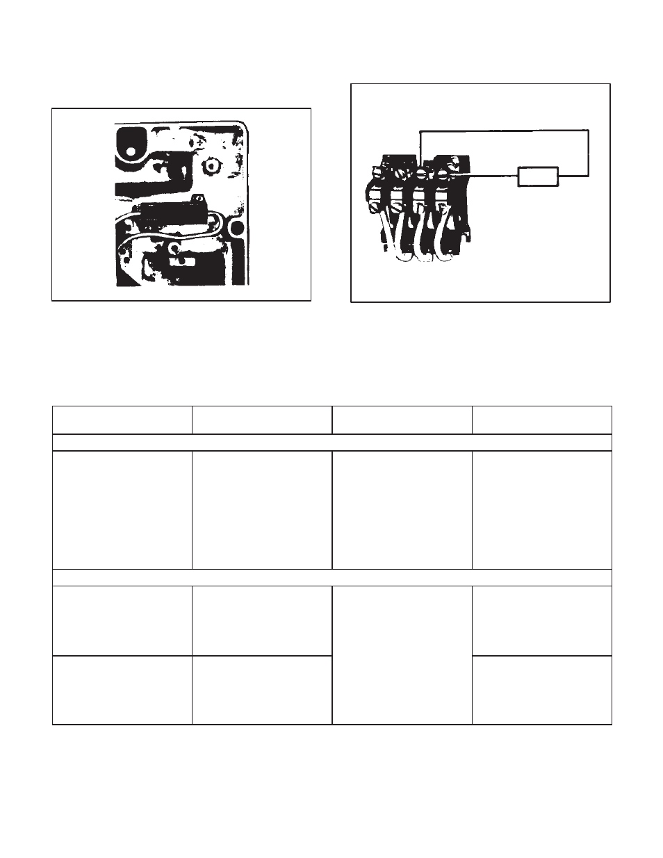
Step 4 Ċ Locate the area of the Chassis where the DyĆ
namic Braking resistor is to be placed. (Refer to Figure
6.5 ) Using the two screws included in the Kit, mount the
resistor onto the Chassis. Place the longer lead pointing
to he nearer Chassis edge.
Figure 6.5 - D.B. Resistor in Chassis
Step 5 Ċ It is necessary to connect both leads to the M
Contactor. Figure 6.6 shows the contactor and the elecĆ
trical connections for the Dynamic Braking resistor.
longer wire
first''
row
M contactor
D.B.
Figure 6.6 - Connecting Dynamic Brake
Table 6.C - WIRE SPECIFICATIONS
USE IN CONTROLLER
TYPE CONDUCTOR
REQUIRED
CHARACTERISTICS
ACCEPTABLE TYPES
CONTROL WIRES
Remote Operator
Control Station:
D AUTO/MANUAL
D JOG/RUN
D FORWARD/REVERSE
D START/STOP
D Single conductor and/or
multiĆconductor
D Stranded copper
D AWG No. 16
D 600 VAC rating
D Insulation: polyĆvinyl
chloride (PVC)
D Temperature range:
40
°
-105
°
C (104
°
-221
°
F)
D Unshielded
D Any single conductor
meeting N.E.C. required
characteristics
SIGNAL WIRE
Remote Operator
Control Station:
D SPEED pot
D TORQUE pot
D ThreeĆconductor
D Twisted with two twists per
inch
D Stranded copper
(19 29)
D AWG No. 16
D 600 VAC rating
D Twist per foot:
D User may twist single
conductors of required
specifications
D Reliance Part No.
417900-79X
D Tachometer Feedback
D Instrument Interface
D Voltage/Tachometer
Follower
D TwoĆconductor
D Twisted pair with two twists
per inch
D Twist per foot:
24 (1/2-inch lay)
D Insulation: polyĆvinyl
chloride (PVC)
D Temperature range:
40
°
-105
°
C (104
°
-221
°
F)
D User may twist single
conductors of required
specifications
D Reliance Part No.
417900-76EAD