Rockwell Automation MinPak Plus DC Drives Kits User Manual
Page 17
16
Table 3.D - HORSEPOWER CALIBRATION
MOTOR HP
MOTOR CURRENT/
PIN CONNECTIONS
115 VAC
230 VAC
PIN CONNECTIONS
1/4
1/3
1/2
3/4
Ċ
Ċ
Ċ
1/2
3/4
1
1Ć1/2
2
3
5
ă2.5A
ă3.7A
ăĂă5A
ă7.5A
10A
15A
25A
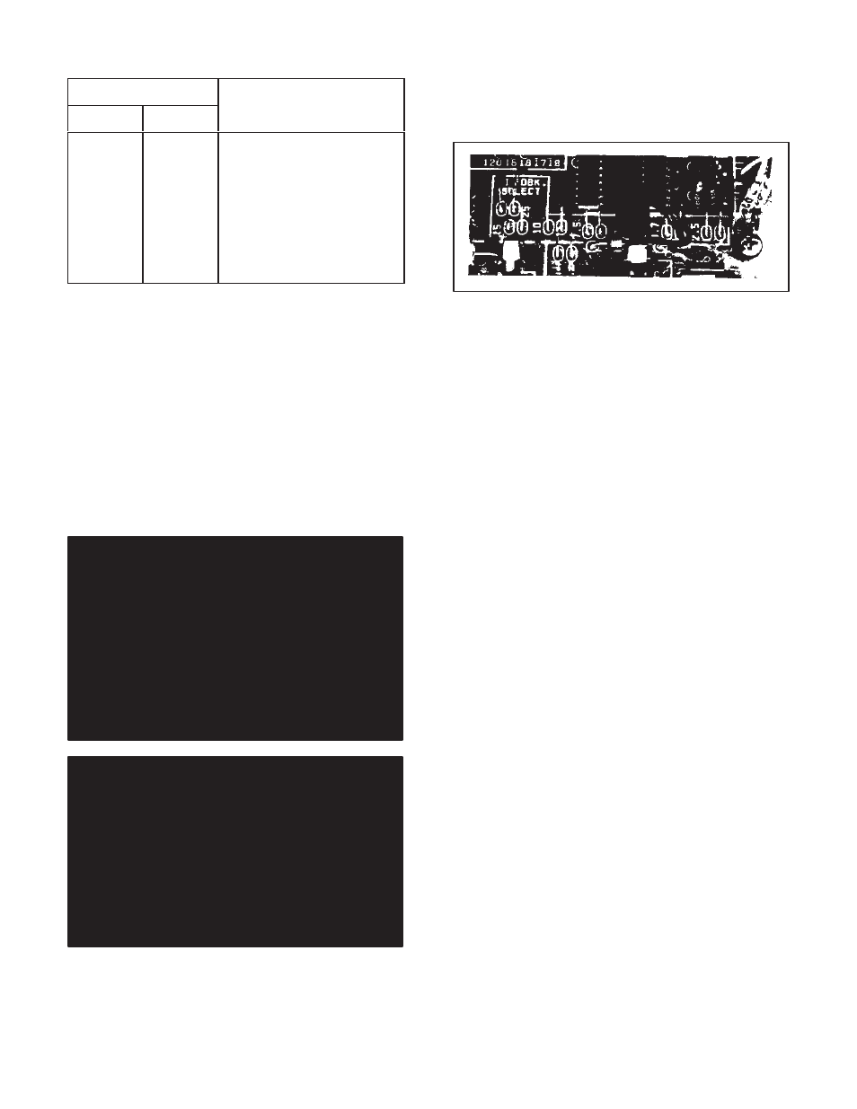
Step 3 Ċ On the Regulator Module, locate the scaling
pins. (Refer to Figure 3.11.) Near them, locate the black
pigĆtail type jumper. Do not move it if it is connected to the
proper pair of pins. If it must be reconnected, carefully lift
it straight up and off the pins. Slide the connector
straight down over the proper set of pins.
Figure 3.11 - HP/Current Scaling Pins
Section 4
STARTĆUP AND ADJUSTMENT
4.0 General Ċ This Section provides startĆup and adĆ
justment procedures to be followed after the assembly
and installation of the controller is complete. All initial opĆ
eration checks and final adjustments to the controller
must be made in conformance to the procedures, warnĆ
ings and recommendations listed here.
DANGER
THE REGENERATIVE MINPAK PLUS CONTROLĆ
LER IS ATLINE VOLTAGE WHEN AĆC LINE POWĆ
ER IS CONNECTED TO THE POWER UNIT INĆ
SIDE THE CONTROLLER. THE OPERATOR'S
POWER ON/OFF CIRCUITBREAKER DOES
NOTREMOVE AĆC LINE POWER FROM THE
UNIT. BEFORE WORKING ON, OR T OUCHING
ANY INTERNAL PARTS F, THE CONTROLLER,
REMOVE INCOMING AĆC LINE POWER ATTHE
MAIN DISCONNECTSWITCH. PERSONAL INĆ
JURY MAY RESULTIF THIS IS NOTFOLLOWED.
DANGER
DURING INITIAL STARTĆUP, THE CONTROLLER
AND ITS ASSOCIATED EQUIPMENT MUST BE
OPERATED AND/OR ADJUSTED ONLY BY
QUALIFIED ELECTRICAL MAINTENANCE PERĆ
SONNEL. THESE INDIVIDUALS SHOULD BE FAĆ
MILIAR WITH THE DESIGN AND OPERATION
OF THIS EQUIPMENT AND WITH THE HAZARDS
INVOLVED. PERSONAL INJURY AND/OR DAMĆ
AGE TO THE CONTROLLER COULD RESULT
FROM UNFAMILIARITY.
Figure 4.1 indicates typical areas in the controller that
should be examined as noted in these paragraphs.
4.1 Power Off Inspection Ċ It is necessary to make a
superficial inspection of the Regenerative MinPak Plus
controller and its associated units. The purpose of this
check is to look for possible physical damage or impropĆ
er connections. These procedures assume that the aĆc
incoming line is locked off and that the load is uncoupled
from the motor.
Step 1 Ċ Inspect the firmness of motor connections.
There should be no broken insulation on power cables
since conductor grounding could cause damage. Make
sure the ground strap between the motor frame and plant
(earth) ground is firmly fixed.
Step 2 Ċ If a formal installation and wiring inspection
was not carried out, it is recommended that an extensive
one be done before any other startĆup procedures are
followed. (Discovery of wiring errors and/or improper or
incomplete assembly will save valuable time later. Refer
to the specific System's layout prints.)
Step 3 Ċ Even if there had been a final inspection, inĆ
spect all wiring, aĆc incoming, dĆc outgoing, feedback,
signal and grounding, for proper and firm connections
Any connection error in wiring can cause damage or a
malfunction when power is applied. Any short to building
ground in signal wiring can also cause damage. Make
sure the open panel or the enclosure is connected to
plant (earth) ground.
Step 4 Ċ Make a final check that the plant power supply
feeding the aĆc line is the proper voltage and frequency.
Step 5 Ċ Use an ohmmeter to determine if a ground exĆ
ists between aĆcinput conductors and the Chassis. Also
determine if a ground exists between dĆcoutput conducĆ
tors and the Chassis. If a ground exists, it must be found
and removed before proceeding.