Rockwell Automation MinPak Plus DC Drives Kits User Manual
Page 39
38
7.6 Schematics, Diagrams Ċ In order to aid with the
troubleshooting process, various schematics and diaĆ
grams are included here. Note that these drawings are
the latest revisions as of the date of publication of this
manual. The manufacturer cannot guarantee that subseĆ
quent changes will not occur; although if any do, they
should be minor. In cases of doubt, contact your local
Reliance Electric Sales Office or Distributor
Included here are the following drawings:
D Figure 7.2 which may be used to locate major
assemblies in the controller. It also lists various
technical data although all of this information is
included in other parts of the manual.
D Figure 7.3 which is a schematic for the controller.
D Figure 7.4 which is a schematic for the Modification
Kits.
D Figure 7.5 which is a simplified control circuit
schematic for a controller.
D Figure 7.6 which is a copy of the screen used to
mark the Regulator Module. It is useful in identifying
locations on the board. Note that areas where
optional Modification Kits fit are marked with heavy
lines.
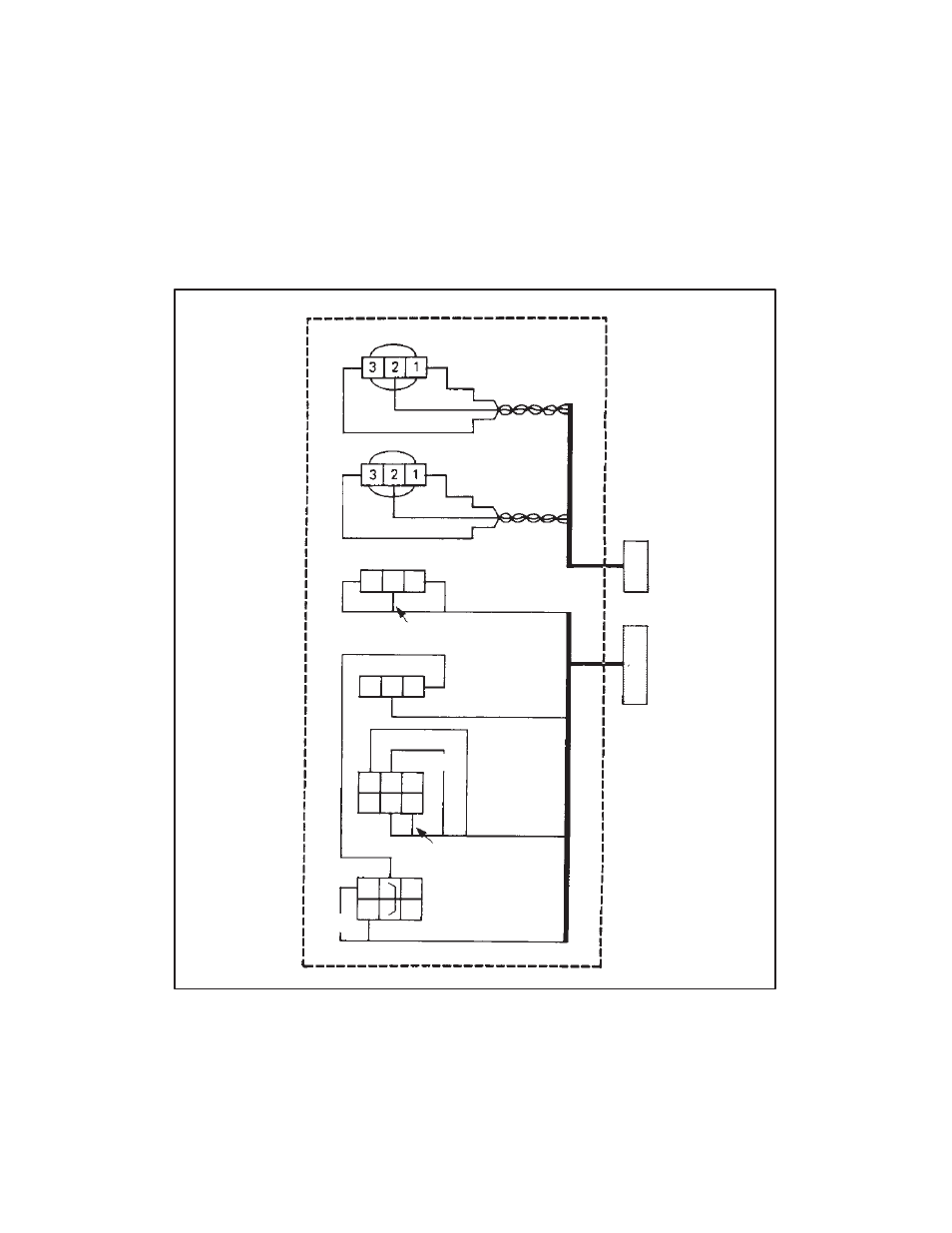
START/STOP
switch
SPEED Pot
TORQUE Pot
AUTO/MANUAL
switch
JOG/RUN
switch
FWD/REV
switch
26
(BLK)
20 (YEL)
26 (BLK)
28 (GRN)
71 (BRN)
57 (RED)
99 (ORG)
326 (GRN)
35 (ORG)
126
(YEL)
67 (GRAY)
71 (WHT)
56
(BLUE)
32
(RED)
67 (PRP)
38 (BRN)
(BLK)
Figure 7.1 - Local Station Connection Diagram