Rockwell Automation MinPak Plus DC Drives Kits User Manual
Page 24
23
Section 5
THEORY OF OPERATION
5.0 General Ċ This Section gives a generalized theory
oaf operation far the Regenerative MinPak Plus controller
It covers internal components and their functions It also
explains the relationship oaf the drive motor and the conĆ
troller.
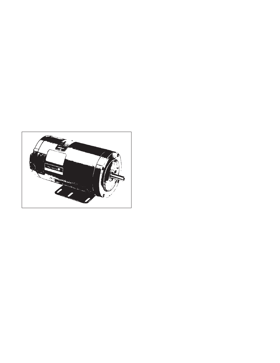
5.1 Motor Ċ A Reliance Electric Super RPMt wound
field dĆc motor is compatible for use with the RegeneraĆ
tive MinPak Plus controller (A typical example is shown
in Figure 5Ć1). The Super RPMt allows adjustable speed
service as a straight shunt machine. It gives constant
shaft torque capability from 50% of base speed to base
speed when provided with fixedĆshunt field excitation
current and a source of adjustable dĆc voltage, such as
the Regenerative MinPak Plus, for armature power (The
permanent magnet Super RPMt dĆc motors do not reĆ
quire a separate field excitation.)
Figure 5Ć1 - Super RPMt Motor (typical)
The fixedĆshunt field provides a constantĆstrength magĆ
netic field against which the armatureĆinduced field can
react Armature (and shaft) speed is then controlled bye
varying the terminal voltage to the armature. Motor
speed is nearly proportional to armature terminal voltĆ
age.
Armature current is drawn, as needed, to provide motor
torque. It is approximately proportional to load torque at
the motor shaft plus a small amount required to support
motor losses.
With the motor's operational needs so described, the
motor controller, here the Regenerative MinPak Plus,
must consist of an adjustableĆvoltage armature supply,
a fixed potential shunt field exciter (for woundĆfield moĆ
tors only), and a regulator to control and adjust armature
voltage under varying torque and speed requirements.
5.2 Armature Rectifier Ċ The armature rectifier, here the
internal Power Cubes in the Regenerative MinPak Plus
controller, consists of two conventional singleĆphase, fullĆ
controlled, fullĆwave bridges. One thyristor bridge is
connected to provide power in the forward direction and
the other is connected to provide power in the reverse
direction. (Refer to Figure 5.2 where it is shown in scheĆ
matic form.) Using four thyristors, the Power Cube proĆ
vides adjustable dĆc voltage for the motor armature cirĆ
cuit by phaseĆcontrolled rectification of singleĆphase aĆc
plant power. Each of the thyristors is turned on" by pulsĆ
ing its gate at a point in the aĆc input power cycle when
its anode potential is positive with respect to its cathode.
Under these conditions, the application of lowĆpower
gate pulse approximately 350 microseconds in duration
will cause the thyristor to conduct for as long as its anode
remains positive with respect to its cathode. AnodeĆtoĆ
cathode polarity reversal, brought about by the sinusoiĆ
dal nature of the incoming plant line, will communicate,
or turn off," the thyristor.
The relative timing of the gate pulse with respect to the
aĆc plant supply will determine the conduction angle
(that is, relative conduction time) of the thyristor and of
the bridge. Thus, the average dĆc output voltage from the
bridge to the motor armature is controlled.
Firing the thyristor gates early in the positive halfĆcycle of
the incoming sinusoid allows it to conduct for a relatively
long time until commutated off by the line. This produces
a relatively high average voltage to the motor armature.
Firing the thyristor gates late in the positive halfĆcycle alĆ
lows only short periods of conduction before commutaĆ
tion. This produces low values of average dĆc output voltĆ
age to the motor armature.
The power module rated at 1/4 thru 3 hp uses two disĆ
crete Power Cubes which contain eight SCRs. Power
modules rated at 5 hp use four Power Cubes each conĆ
taining two SCRs. (Refer to Figure 5.3 where a typical
Power Cube is shown.)
The mechanical design of the Regenerative MinPak Plus
Power Cube provides excellent heatĆtransfer characterisĆ
tics. Because of its modular design, the small unit is easiĆ
ly replaced.
5.3 Gating Sequence, Current Flow Ċ The basic fullĆ
wave, fullĆcontrol rectifier bridge is shown in Figure 5.2.
Power Unit #1 is used for motoring and Power Unit #2
for regenerating with forward rotation of the motor shaft.
The opposite is true for the reverse motor shaft rotation.
The following gate sequence is for forward motoring opĆ
eration (Power Unit #1 ON). When L1 (181) is positive
with respect to L2 (182), current flows through thyristor
3, on through the motor armature, and, when the gates
to thyristors 3 and 2 are gated ON, through thyristor 2.
Conversely, when L2 (182) is positive with respect to L1
(181), current flows through thyristor 4, on through the
motor armature, and to thyristor 1 when the gates to thyĆ
ristors 4 and 1 are gated ON.
A unique Reliance Electric circuit prevents both Power
Units from being turned ON at the same time and, in
addition, prevents both sets of thyristors (3 and 2 and 4
and 1) from being gated ON at the same time. This
guards against a short circuit.