Rockwell Automation MinPak Plus DC Drives Kits User Manual
Page 12
11
Earth ground is defined as the central ground for all elecĆ
trical and aĆc power within a facility. Frequently earth
ground may also be the plant, magnetics, equipment,
electrical, circuit, neutral or reference ground, dependĆ
ing on the nomenclature used at a facility.
Copper wire, preferably braided, should be used beĆ
tween the cabinet and the earth ground connections. All
ground circuits must be continuous (that is, not broken)
and permanent.
Chassis ground is defined as any electrical connection
to the metal body of the unit, here the controller. Since
each Chassis eventually connects to earth ground, all
units in a control system have a single common referĆ
ence point.
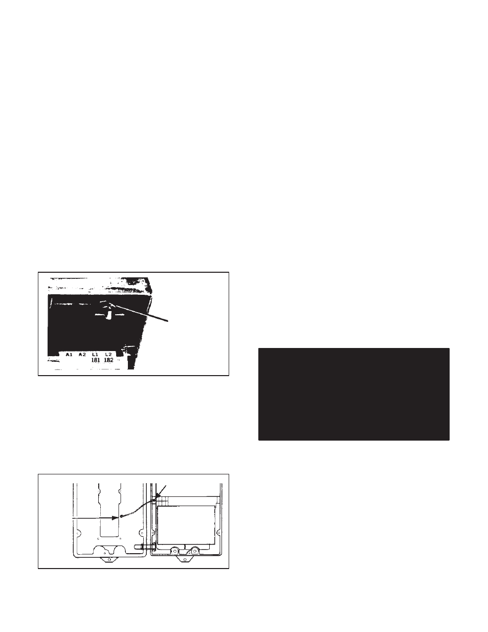
3.3.1 AĆC Network Ground Ċ One type of Chassis
ground involves the aĆc network ground. The incoming
aĆc power line should have three conductors: L1 (red), L2
(white on 115 V) and GND (green). The ground wire
must be firmly connected to the Chassis terminal proĆ
vided. Use a ring connector to assure a permanent conĆ
nection. (Refer to Figure 3.5.)
Note that the aĆc ground must not in any way be broken
between the power source and the Chassis. (The recomĆ
mended disconnect switch must not break the GND
conductor.)
Ground terminal
(green)
Figure 3.5 - Chassis AĆC Ground Terminal
3.3.2 Cover Grounding Ċ A ground wire, supplied as
standard with each Faceplate, must be connected to a
bolt on the underside of the Cover, if used. (Refer to FigĆ
ure 3.6.) The function of this wire is to carry the ground
circuit protection to the operator switches and external
shell. (It must be used with both Local and Remote ConĆ
trol Stations.)
User
attaches
wire
here.
Figure 3.6 - Cover Ground Wire
Since the green wire is fixed by the user on a Faceplate
bolt, the installation should be performed when the FaceĆ
plate is fitted. Full details are given at Paragraph 6.1 for
the Local Station and Paragraph 6.2 for the Remote.
3.4 Conduits Ċ In general, steel conduits must be used
on power and signal conductors entering the controller
Chassis. When properly installed, they maintain the
NEMA Type 4/12 rating. Make sure to turn the connecĆ
tions a minimum of eight turns.
The Chassis has five conduit wells, three at the top and
two at the bottom. Each is dedicated to a specific funcĆ
tion. The five wells are:
D AĆc incoming voltage
D DĆc outgoing voltage
D Tachometer feedback (optional)
D Remote Station (optional)
D Process control or auto reference (optional)
Refer to Figure 3.7 for locations.
Each well has a knockout pad'' which may be easily
punched out. Make sure only those pads used with the
application are removed.
If a pad is accidentally punched out, the well must be
sealed in order to maintain the washĆdown'' characterĆ
istics. Use a pipe plug with Teflon tape, or equivalent
sealant.
Due to space limitations, it is recommended that all wires
be drawn into the controller, not the opposite.
3.5 Power Wiring Ċ This Paragraph briefly outlines the
procedures to be followed when wiring aĆc power supply
lines to the controller and dĆc control circuits to the drive.
Consult the basic connection diagram (Figure 3.8) closeĆ
ly when following these steps.
DANGER
BEFORE WIRING, MAKE SURE THE AĆC LINE
DISCONNECT SWITCH IS LOCKED OPEN.
EVEN IF POWER HAS NOT BEEN APPLIED TO
THE INCOMING LINE, THIS PRACTICE ASĆ
SURES PERSONAL SAFETY. IF NO LOCKOUT
DEVICE EXISTS, REMOVE THE FUSES WITH AN
INSULATED TOOL AND PLACE A WARNING
TAG ON THE BOX.
All interconnecting wire should primarily be sized and
installed in conformance with N.E.C. or local codes. ReĆ
fer to the controller and motor nameplates for electrical
data. Typical wire sizes and types are listed in Table 3.A
as a basic guideline. Note that long cable runs may reĆ
quire that a larger gauge be used to avoid excessive voltĆ
age drop. Use of stranded wire is also recommended.
3.5.1 AĆC Wiring Ċ Draw the aĆc line conductors into the
Chassis. Make sure Guidelines 1 1, 12, 13, 14, 15, 16 and
17 have been considered. Wire according to Figure 3.8.
After wiring, examine all terminals to determine that conĆ
nections are correctly made at both ends. Confirm wire
identification. Examine the firmness of the connections.