Rockwell Automation MinPak Plus DC Drives Kits User Manual
Page 33
32
Step 1 Ċ Make the same assumption as in Paragraph
6.5.1, Step 2.
Step 2 Ċ Connect the black pigĆtail jumper on the InterĆ
face Module to the 50 mA pin. (Refer to Figure 6.10.)
Step 3 Ċ Locate the Auto Minimum Speed potentiomeĆ
ter on the Interface Module. Turn it CW to the third dot
which represents aoneĆthird turn.
Step 4 Ċ Place the controller in the AUTO mode, if so
equipped Locate the Auto Maximum Speed potentiomeĆ
ter. Adjust it to obtain the desired preset speed. (CW inĆ
creases speed, CCW decreases it.)
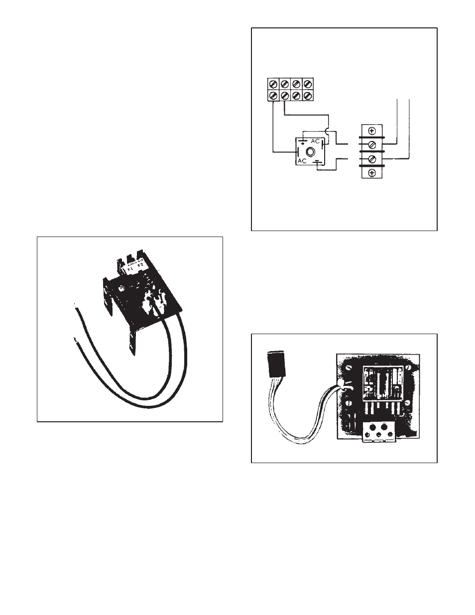
6.6 Field Supply Ċ The Field Supply Kit provides fullĆ
wave field excitation for shuntĆwound dĆc motors. (Refer
to Figure 6.11.) It may be optionally applied to controllers
from 1/4 thru 1Ć1/2 hp. (It is a standard feature for 2, 3 and
5 hp Regenerative MinPak Plus controllers.)
DĆC field supply voltage and maximum field amperes are
listed in Table 2.D.
The Kit is an assembly consisting of a terminal block, a
Field Supply Power Cube, two wire harnesses, and a
Mounting Bracket. The user provides the F1/F2 conducĆ
tors to the drive motor. No other equipment is required.
Figure 6.11 - Field Supply Kit
To install the Kit, follow these procedures.
Step 1 Ċ Mount the assembly bracket to the top of the
circuit breaker bracket with the screws securing the cirĆ
cuit breaker.
Step 2 Ċ Wire from the Field Supply Power Cube to terĆ
minals 51 and 52 on 2TB by passing the wires under the
circuit breaker bracket.
Step 3 Ċ If Paragraph 3.5.2 was followed, the user supĆ
plied field wiring conductors should be drawn into the
Chassis. Route them as indicated in Figure 3.7. Move
them to the screws on 3TB and connect F1/F2 according
to the la bel or Figure 6.12.
51
To
F1, F2
on motor
52
2TB
3TB
F2
F1
Figure 6.12 - Connecting Field Supply
6.7 Auxiliary M Contacts Ċ With the optiona l Auxilia ry
M Contact Kit, the ON/OFF status of the Regenerative
MinPak Plus is able to be interlocked with userĆsupplied
devices. (Refer to Figure 6.13.) Typical applications inĆ
clude pilot/indicator lights, alarms, and interlocking with
other control circuits dependent on the drive system.
Figure 6.13 - Auxiliary M Contactor Kit
The Kit provides asingle pair of Form C contacts, one
normally open (NO) and one normally closed (NC). Both
share a common terminal. (Refer to Figure 6.14) These
contacts function when the M contactor is energized.
The Kit contains only a Module that has a wire harness
attached.