Rockwell Automation MinPak Plus DC Drives Kits User Manual
Page 11
10
Use a 1Ćinch copper braid or an 8 gauge wire and conĆ
nect with the plant (central) ground.
The motor frame should also be grounded. In many
cases it is adequate to use a screw in the conduit box
near the motor .
Guideline 19 Ċ A thermostat is used to guard against
motor overload protection. It is essential to properly conĆ
nect the motor thermostat in series with the Operator's
Control Station STOPselector switch at connections 32
and 132. (Refer to Paragraph 3.6 for specific details. ReĆ
fer also to Figure 3.8 in which a typical Operator's Control
Station schematic is shown.)
Guideline 20 Ċ When planning signal or control wire
runs, as listed in Table 6.C, follow these practices:
D Conduits should be steel.
D If these conduits cross 440 VAC conductors, make
sure the cross is at 90
°
.
D Do not route signal wires through junctions or
terminal boxes that contain nonĆsignal aĆc or dĆc
(115/230/460 V) wires.
Guideline 21 Ċ Operational altitude above sea level
may not exceed 3300 ft (1000 m). Derate horsepower 3%
for each 1000 ft (300 m) above this altitude.
3.2 Mounting Ċ This Paragraph outlines the proceĆ
dures to be followed in order to mount the Regenerative
MinPak Plus controller . It assumes that a layout plan exĆ
ists and that Guidelines 1, 2, 3, 4, 5, 7 and 9, noted in
Paragraph 3.1, have been considered.
The three largest components of the Regenerative MinĆ
Pak Plus controller are the Chassis, the Cover and a CovĆ
er Faceplate. The first two items are standard; the third
is specified and ordered as an option.
If the Cover is not being used, it should be removed beĆ
fore mounting begins. (It may be unfastened at the
hinges.)
CAUTION: The controller design requires that the
Cover be lifted about 2 inches (50 mm) directly up
from the Chassis before it may be swung to one
side. Always be careful to lift it before hinging to the
side. Damage to the unit may result if this practice is
not followed.
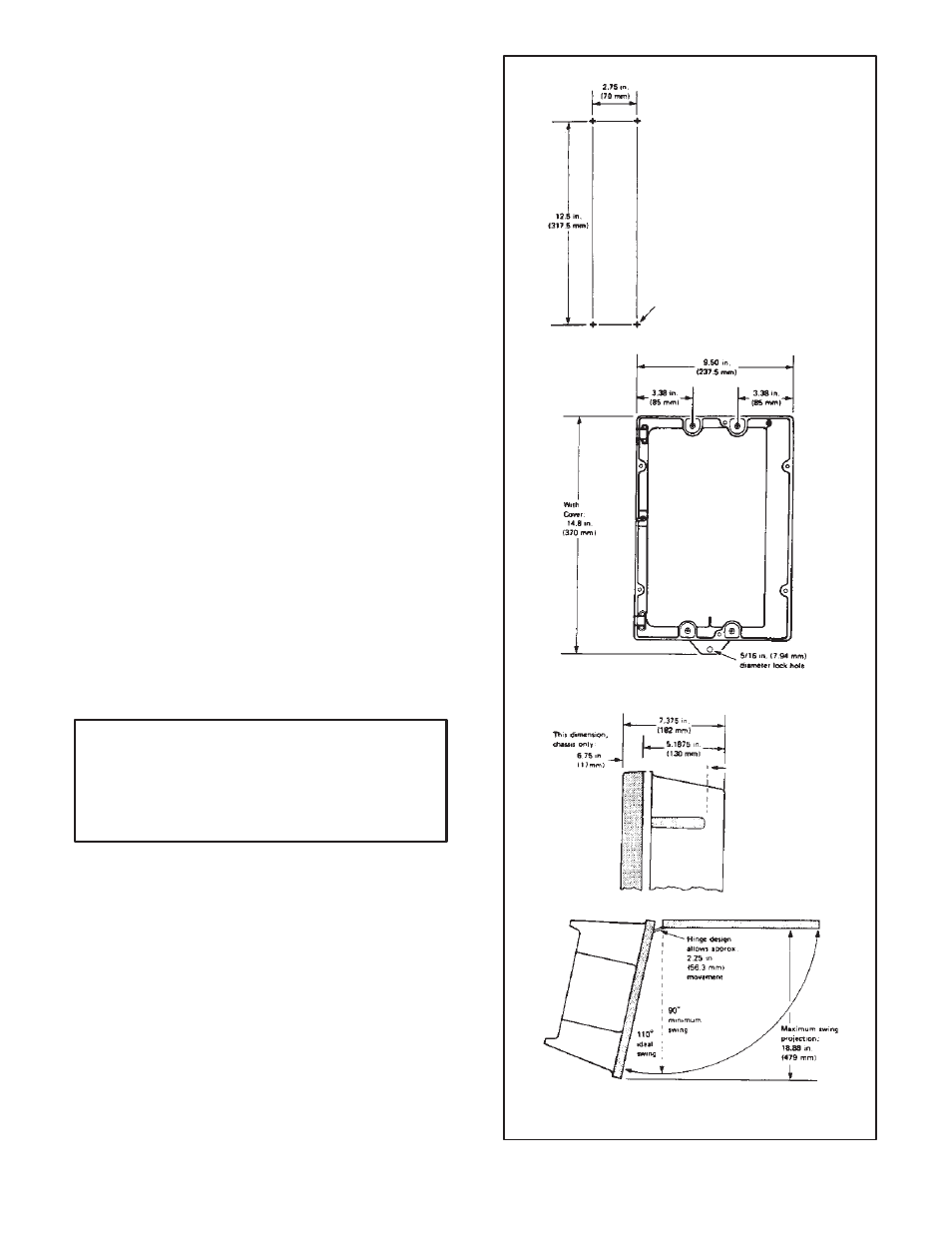
Determine the exact placement of the Chassis on the wall
or panel. (Refer to Figure 3.4 for mounting dimensions.)
Scribe the panel or mark the wall. Drill four holes large
enough to accept 1/4 inch mounting bolts. Scrape the
paint around the holes to allow washers and bolts to
make a ground contact.
Choose four 1/4"-20 lug bolts. Their length depends
upon the depth of the entire mounting surface. Because
of the Chassis design, only 1/8 inch (3 mm) is required
between the inside of the well and the outside edge of the
heat sink.
3.3 Grounding Ċ Proper grounding practices are esĆ
sential to assure personal safety, to guard against electriĆ
cal shocks to personnel who touch the exterior surfaces
of the controller or enclosures and to reduce the effects
of electrical noise interference on signalĆtype circuits.
There are two basic types of grounds: earth and chassis.
a) mounting drill plan
b) overall dimensions
c) side view
d) top view
Scrape
paint
around
holes
to assure
grounding.
Drill 4
holes
for 1/4” – 20
lug
screws.
Figure 3.4 - Mounting Dimensions