Rockwell Automation MinPak Plus DC Drives Kits User Manual
Page 19
18
If aRemote Station is used. aseries of wires will connect
to individual terminals on a strip mounted on the Remote
Operator Interface Module. (This Module is mounted on
the Regulator Module. Refer to Figure 4.1.) Determine
that all wires are firmly seated in the terminal strip. Make
sure all wires are connected.
4.2.2 50ĆHz Resistors Ċ Although the Regenerative
MinPak Plus operates without modification with a 50ĆHz
frequency input, there are performance advantages if
two resistors are removed. If 50ĆHz operation is exĆ
pected, make sure the resistors are removed. (Refer to
Figure 3.10.)
4.2.3 Regulation Mode Jumper Ċ The Regenerative
MinPak Plus controller offers two types of drive regulaĆ
tion. The first, which is factory shipped, is an armature
voltage feedback (A). Optionally, the user may use
tachometer feedback (T). In order to use the tachometer
feedback, the Regulation Mode Jumper, one end of
which is permanently fixed to the Regulator Module,
must be moved to the T" position. (Refer to Figure 3.9.)
Details of Jumper placement are noted in Section 3.
DANGER
IF YOU ARE UNSURE WHICH REGULATION
MODE A CONTROLLER SHOULD HAVE, IT IS
IMPORTANT YOU FIND OUT. IF THE JUMPER IS
NOT PROPERLYCONNECTED, PERSONAL INĆ
JURYMAYRESULT.
4.2.4 Remote Station, Tachometer Grounds Ċ When
a Remote Operator Station or a tachometer device or an
instrument interface device is being used. it is necessary
to carefully check for possible grounds between the metĆ
al base and the magnetic control circuits. This procedure
should be followed only if one of the three devices is beĆ
ing used. (If the Operator Station switches are mounted
on the Regenerative MinPak Plus controller's Cover, do
not follow this procedure. If there is no tachometer or
instrument interface device. do not follow them.)
CAUTION: Do not use amegger to perform these
checks since some electrical circuits connected to
test points could be damaged by the high voltage of
the megger.
CAUTION: A ground between the control circuits or
associated wires and the grounded parts of the
controller will cause improper operation. Follow
this procedure carefully.
Step 1 Ċ On an ohmmeter, set up for an R x 100,000
scale.
Step 2 Ċ Connect one ohmmeter lead to the controller's
Chassis to make a simple resistance check.
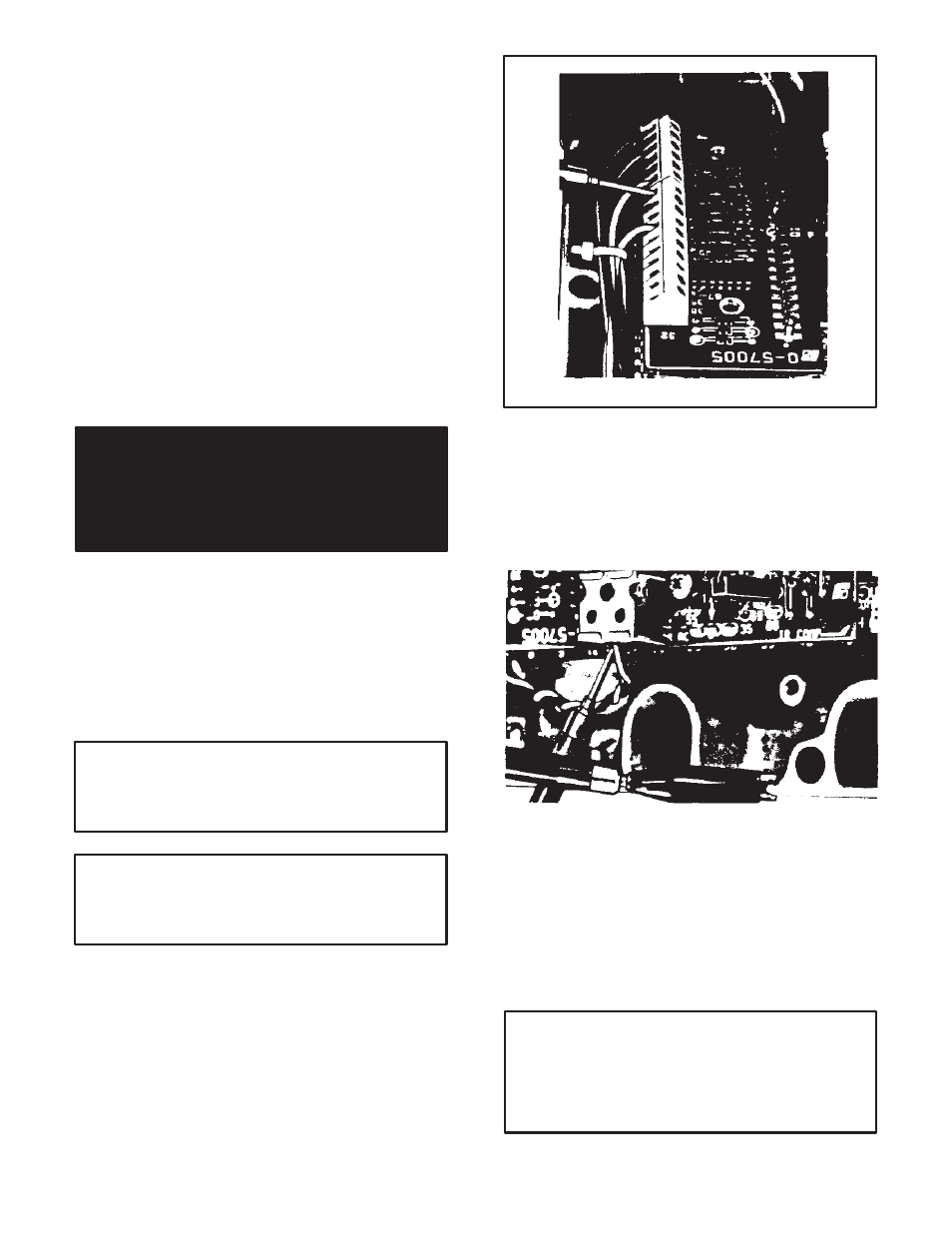
Step 3 Ċ On the Remote Operator Module, touch the
test probe to each screw terminal on the terminal strip.
Do this in an orderly fashion. (Refer to Figure 4.3.) If a
reading to ground on any terminal is less than 100,000
ohms, aground condition exists in this circuit.
Figure 4.3 - Testing Remote Module
Step 4 Ċ On the Tachometer Feedback Module, touch
the two screw terminals, (+,-) on the terminal strip. (ReĆ
fer to Figure 4.4.) If the reading to ground on either termiĆ
nal is less than 100,000 ohms, a ground condition exists
in this circuit.
Figure 4.4 - Testing Tachometer Feedback
Step 5 Ċ Should aground condition be found, consult
the wiring diagram in Figure 3.8. Examine both ends of
the signal wires for bare wire touching. (This may be due
to excess stripping or insulation breaks.)
4.2.5 Motor Ground Check Ċ It is necessary to make
a check of the drive motor to assure that no damaging
groundsĊother than earth groundĊexist with in the
motor.
CAUTION: Although amegger may be used for this
test, if one is used, all conductors between the drive
motor and the Regenerative MinPak Plus controller
are to be disconnected and moved aside. The high
voltage of the megger can cause damage to the
controller's circuits.