Rockwell Automation MinPak Plus DC Drives Kits User Manual
Page 37
36
Step 4 Ċ Using three twisted wires, connect the user
supplied 5 K ohm Dancer potentiometer to the terminal
strip of the Dancer Follower Module. The speed inĆ
crease side of the potentiometer connects to terminal
556 and the speed decrease side connects to terminal
571. The potentiometer wiper is connected to terminal
919.
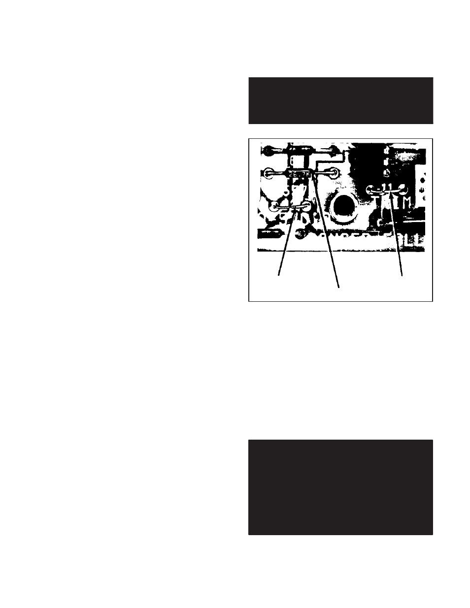
Step 5 Ċ If an optional Dancer Position potentiometer
is used (supplied by user), connect the up'' side of the
potentiometer to terminal 726 of the Dancer Follower
Module and the down" side to terminal 557. Connect
the potentiometer wiper to terminal 926. Also cut and reĆ
move jumper J2 and the 26.7 K resistor (R6) on the
Dancer Follower Module. (Refer to Figure 6.20.)
Step 6 Ċ If an AUTO/MANUAL selector switch is used
on the Operator Control Station, remove jumper J1 of
the Dancer Follower Module. (Refer to Figure 6.20.) If,
however, the controller is to run automatically without
manual speed control, leave J1 in place.
Step 7 Ċ This Step assumes that the complete drive
system, including the controller, has been successfully
started and debugged according to Section 4 thru ParaĆ
graph 4.4.1. It is now necessary to conduct a powerĆon
test.
Start the drive and place it in the AUTO mode, if so
equipped. With the line speed reference at maximum
value, adjust the MAX SPEED TRIM potentiometer on
the Dancer Follower Module for maximum motor speed.
If the optional Dancer Position potentiometer is
installed, place it in the midĆrange.
Turn the GAIN potentiometer of the Dancer Follower
Module fully counterclockwise for minimum Dancer poĆ
tentiometer response. Turn the GAIN potentiometer
clockwise in small increments to increase the Dancer poĆ
tentiometer response.
DANGER
APPLICATION MUST NOT RELY ON ZERO
SET/INPUT SETTING FOR SAFETY. SERIOUS
ORFATAL INJURY MAY RESULT.
Resistor (R6)
Jumper J2
Jumper J1
Figure 6.20 - Jumpers J1, J2 and Resistor (R6)
Section 7
TROUBLESHOOTING
7.0 General Ċ This Section details troubleshooting inĆ
formation for the Regenerative MinPak Plus controller. Its
organization is as follows:
D General troubleshooting concepts (Par. 7.1, 7.2,
7.3, 7.4)
D Specific symptom/probable cause/recommended
procedures (Par. 7.5)
D Reference schematics of the controller (Par. 7.6)
DANGER
CONTROLLER EQUIPMENT IS AT LINE VOLTĆ
AGE WHEN AĆC POWERIS CONNECTED TO
THE POWER UNIT IN THE REGENERATIVE MINĆ
PAK PLUS CONTROLLER. THUS AĆC POWER
MUST BE REMOVED FROM THE UNIT BEFORE
IT IS SAFE TO TOUCH THE INTERNAL PARTS
OF THE REGENERATIVE MINPAK PLUS. PERĆ
SONAL INJURY MAY RESULT UNLESS POWER
IS REMOVED.