Bit-strobe message format – Rockwell Automation 1440-VDRP06-00RH XM-160/161/162 Direct Vibration Module User Manual
Page 97
Publication GMSI10-UM025C-EN-P - August 2010
DeviceNet Information 89
XM Status Values
The following tables describe the XM Status values that are included in the
COS messages.
Bit-Strobe Message Format
The Bit-Strobe command sends one bit of output data to each XM slave
whose node address appears in the master’s scanlist.
The Bit-Strobe command message contains a bit string of 64 bits (8 bytes) of
output data, one output bit per node address on the network. One bit is
assigned to each node address supported on the network (0...63) as shown in
Figure B.1.
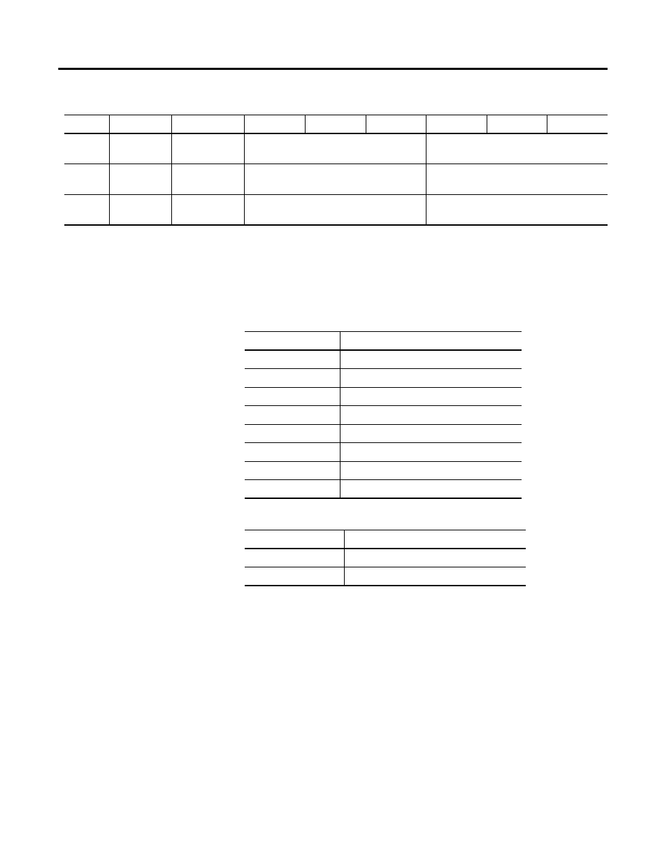
5
Relay 6
Status
Reserved
Reserved
Reserved
6
Relay 7
Status
Reserved
Reserved
Reserved
7
Relay 8
Status
Reserved
Reserved
Reserved
XM-160/161/162 COS Message Format
Byte
Bit 7
Bit 6
Bit 5
Bit 4
Bit 3
Bit 2
Bit 1
Bit 0
Alarm Status Descriptions
Alarm Status Value
Description
0
Normal
1
Alert
2
Danger
3
Disarm
4
Transducer Fault (Sensor OOR)
5
Module Fault
6
Tachometer Fault
7
Reserved
Relay Status Descriptions
Relay Status Value
Description
0
Not Activated
1
Activated