Module indicators – Rockwell Automation 1440-VDRP06-00RH XM-160/161/162 Direct Vibration Module User Manual
Page 62
Publication GMSI10-UM025C-EN-P - August 2010
54 Installing the XM-160/161/162 Direct Vibration Module
2. Make certain the side connector (B) is pushed all the way to the left. You
cannot install the module unless the connector is fully extended.
3. Make sure that the pins on the bottom of the module are straight so they
will align properly with the connector in the terminal base unit.
4. Position the module (D) with its alignment bar (E) aligned with the
groove (F) on the terminal base.
5. Press firmly and evenly to seat the module in the terminal base unit. The
module is seated when the latching mechanism (G) is locked into the
module.
6. Repeat the above steps to install the next module in its terminal base.
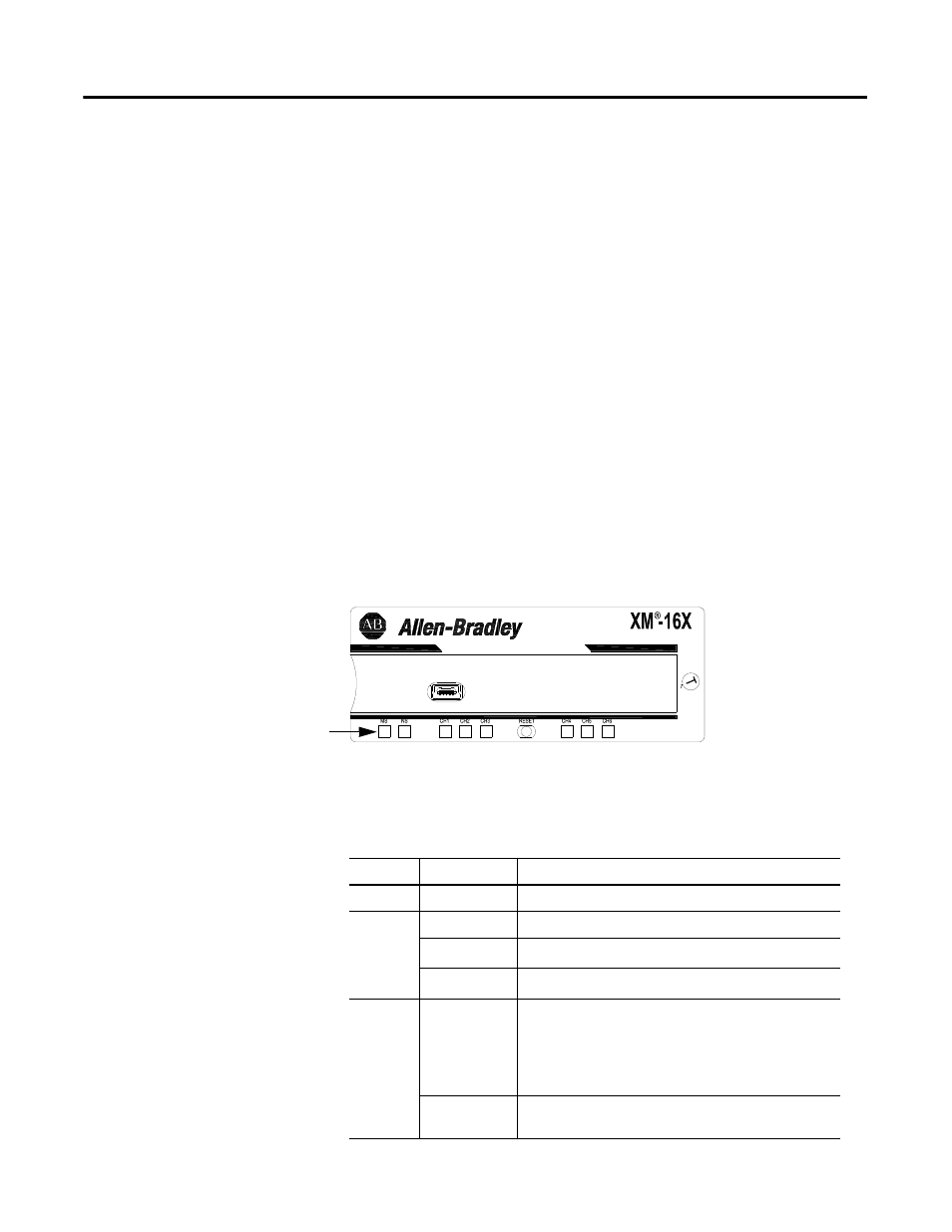
Module Indicators
Each Direct Vibration module has eight LED indicators, which include a
module status (MS) indicator, a network status (NS) indicator, and a status
indicator for each channel (CH1 to CH6). The LED indicators are located on
top of the module.
Figure 2.46 LED Indicators
The following tables describe the states of the LED status indicators.
Module Status (MS) Indicator
1440-VDRx06-0xRH
Module Indicators
Color
State
Description
No color
Off
No power applied to the module.
Green
Flashing Red
Module performing power-up self test.
Flashing
Module operating in Program Mode
1
.
Solid
Module operating in Run Mode
2
.
Red
Flashing
• Application firmware is invalid or not loaded.
Download firmware to the module.
• Firmware download is currently in progress.
• The module power voltage is incorrect.
Solid
An unrecoverable fault has occurred. The module may
need to be repaired or replaced.