Rockwell Automation 1440-VDRP06-00RH XM-160/161/162 Direct Vibration Module User Manual
Page 69
Publication GMSI10-UM025C-EN-P - August 2010
Configuration Parameters 61
Eng. Units
Defines the native units of the transducer. Your
choice controls the list of possible selections
available in the Output Data Units parameter. It
also affects other module parameters.
Fault Low
The minimum, or most negative, expected DC
voltage from the transducer.
Volts
Note: A voltage reading outside this
range constitutes a transducer fault.
Fault High
The maximum expected DC bias voltage from the
transducer.
DC Bias Time Constant
The time constant used for exponential averaging
(low pass filtering) of the transducer DC bias
measurement. The corner frequency for the low pass
filter is 1 / (2
π
x DC Bias Time Constant). The
greater the value entered, the longer the settling
time of the measured value to a change in the input
signal. See example table below.
Seconds
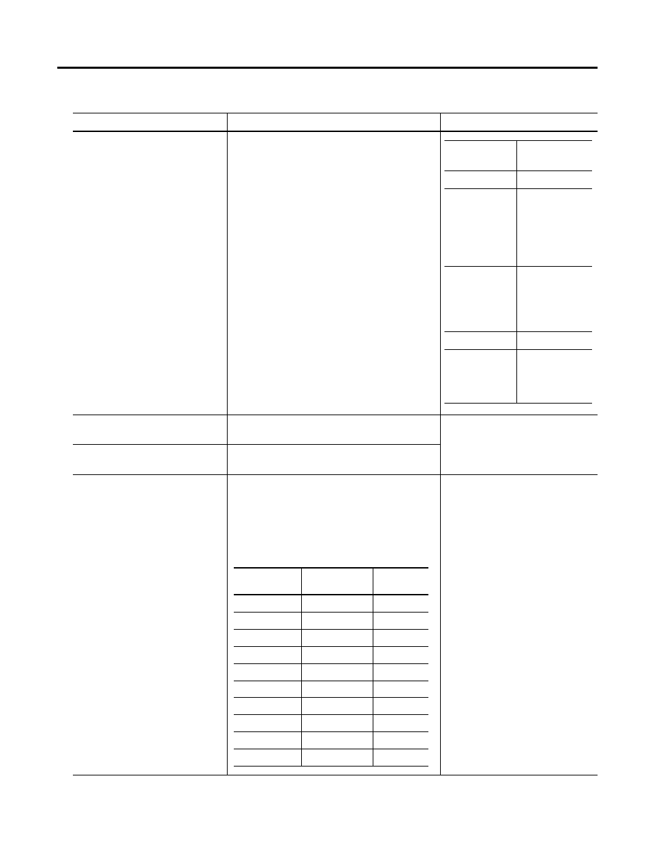
Channel Transducer Parameters
Parameter Name
Description
Values/Comments
Eng. Units
Options
Quantity of
Measure
g (gravity)
Acceleration
ips (inch per
second)
mm/s
(millimeters per
second)
Velocity
mils (1/1000
inch)
um (micro
meter)
Displacement
Volts
Voltage
Pa (pascals)
psi (pound-force
per square inch)
pressure
Time Constant
(seconds)
-3dB Frequency
(Hz)
Settling
(seconds)
1
0.159
3
2
0.080
6
3
0.053
9
4
0.040
12
5
0.032
15
6
0.027
18
7
0.023
21
8
0.020
24
9
0.018
27
10
0.016
30