Connecting a passive transducer, Important – Rockwell Automation 1440-VDRP06-00RH XM-160/161/162 Direct Vibration Module User Manual
Page 47
Publication GMSI10-UM025C-EN-P - August 2010
Installing the XM-160/161/162 Direct Vibration Module 39
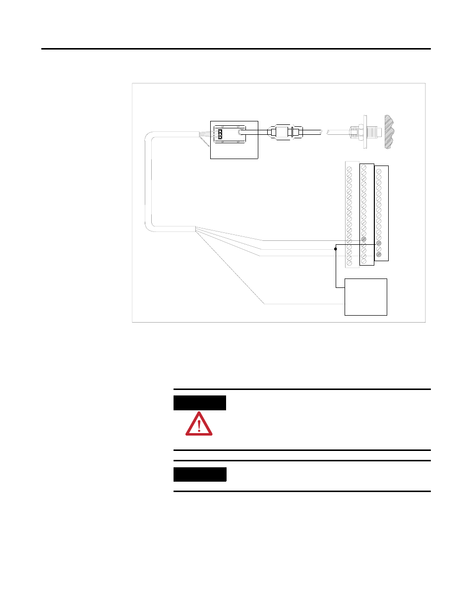
Figure 2.31 Non-Contact Sensor to XM-160/161 Channel 6 Wiring
Connecting a Passive Transducer
The figures below show the wiring of a passive transducer, such as a velocity
sensor, to the terminal base unit.
TYPICAL WIRING FOR NON-CONTACT SENSOR
TO XM-160/161 DIRECT VIBRATION MODULE CHANNEL 6
COM
SIG
-24
Channel 6 Input Signal
-24V DC
Signal Common
29
13
Isolated Sensor Driver
Shield
Shield
Floating
+
-
+24V DC
Isolated
Power
Supply
15
ATTENTION
You may ground the cable shield at either end of the cable.
Do not ground the shield at both ends. Recommended
practice is to ground the cable shield at the terminal base
and not at the transducer. Any convenient Chassis terminal
may be used (see Terminal Block Assignments on page 17).
IMPORTANT
The module does not power the sensor. It measures only
the input voltage.