Connecting wiring for your module, Terminal block assignments – Rockwell Automation 1440-VDRP06-00RH XM-160/161/162 Direct Vibration Module User Manual
Page 25
Publication GMSI10-UM025C-EN-P - August 2010
Installing the XM-160/161/162 Direct Vibration Module 17
Connecting Wiring for Your
Module
Wiring to the module is made through the terminal base unit on which the
module mounts. The XM-160, XM-161, and XM-162 modules are compatible
only with the XM-947 terminal base unit, Cat. No. 1440-TB-H.
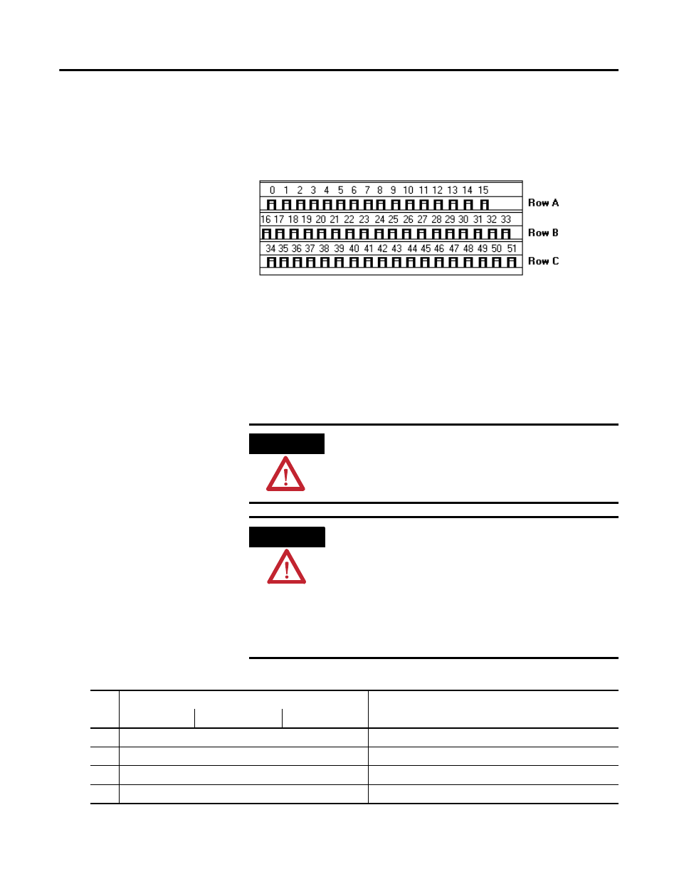
Figure 2.7 XM-947 Terminal Base Unit
Terminal Block Assignments
The terminal block assignments and descriptions for the XM-160, XM-161,
and XM-162 modules are shown below.
ATTENTION
The terminal block assignments are different for different
XM modules. The following table applies only to the Direct
Vibration modules. Refer to the installation instructions for
the specific XM module for its terminal assignments.
WARNING
EXPLOSION HAZARD
Do not disconnect equipment unless power has been
removed or the area is known to be nonhazardous.
Do not disconnect connections to this equipment unless
power has been removed or the area is known to be
nonhazardous. Secure any external connections that mate
to this equipment by using screws, sliding latches, threaded
connectors, or other means provided with this product.
XM-947, Cat. No. 1440-TB-H
Terminal Block Assignments
Name
No.
XM-160
XM-161
XM-162
Description
0
Chassis
Connection to DIN rail ground spring or panel mounting hole
1
Chassis
Connection to DIN rail ground spring or panel mounting hole
2
Chassis
Connection to DIN rail ground spring or panel mounting hole
3
Signal Common
Transducer input and buffered output return